北京地铁6号线东大桥站基坑支护设计(含CAD图)

北京地铁6号线东大桥站基坑支护设计(含CAD图)(任务书,开题报告,论文计算书27000字,CAD图8张)
摘 要
东大桥站位于东大桥路口东侧,朝外大街、工体东路、东大桥路、朝阳北路及朝阳路五条道路交汇与此形成五叉路口,该区域是朝阳地区重要的客流集散点,地面交通十分繁忙。地铁车站设置在公交站场及以东的朝阳北路下,东西走向。
东大桥站为三层岛式车站,有效站台宽13m,长158m,地下一层为地铁站厅层,地下二层为地铁设备层、地下三层为地铁站台层。主体结构采用双柱三跨结构,车站总长175m。车站标准段结构宽22.1m,高19.4m,覆土2.5~3.0m。
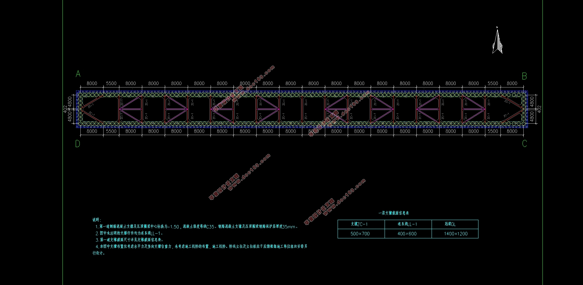
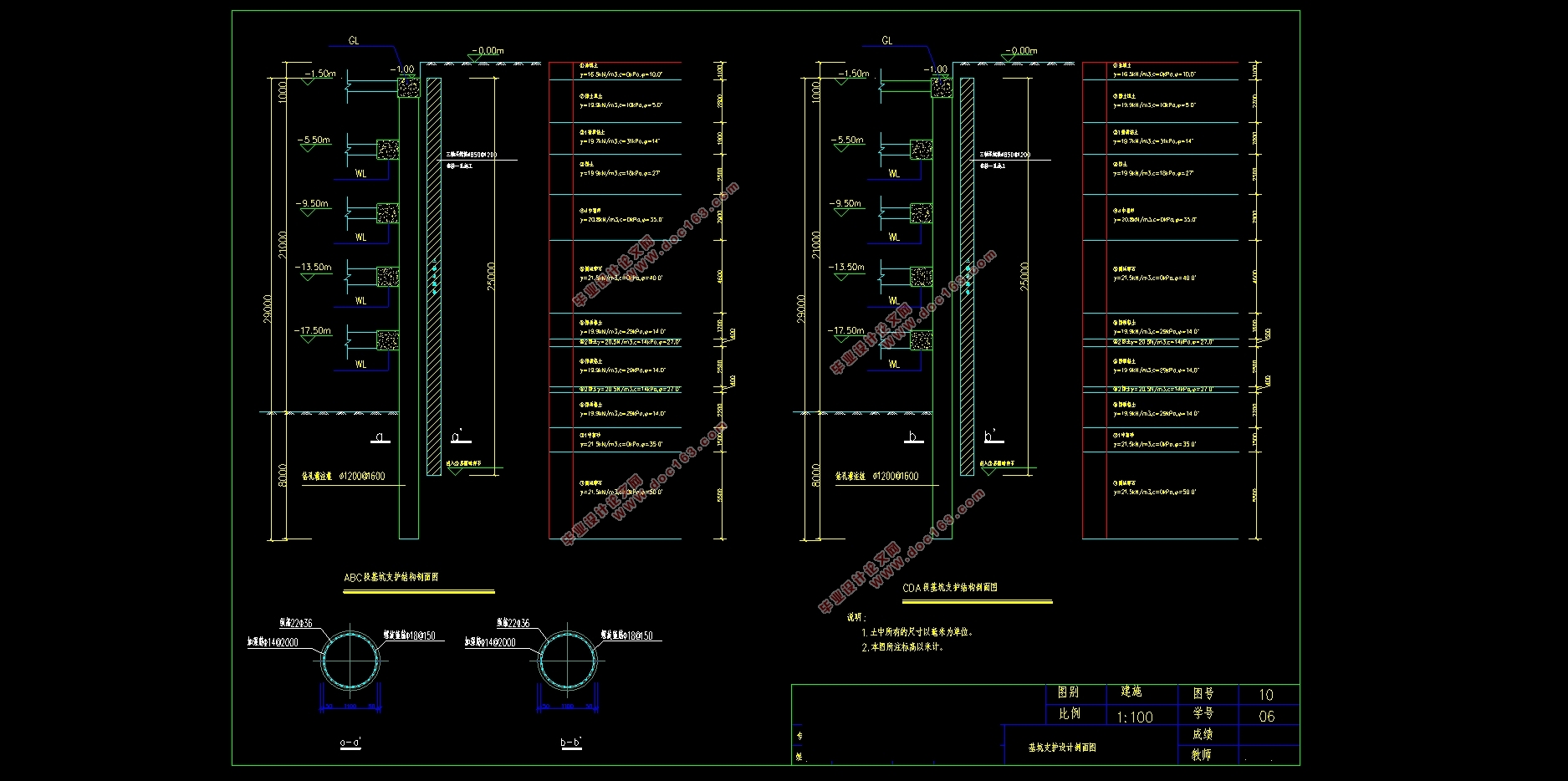
考虑基坑周边环境对支护结构变形的敏感性,本着“安全可靠,经济合理,技术可行,施工方便”的原则,基坑采用钻孔灌注桩+水泥土搅拌桩止水帷幕的围护结构;内支撑系统水平向采用五道道均为对撑、角撑结合边桁架的支撑体系,竖向采用柱下钻孔灌注桩作为水平支撑系统的竖向支承构件。基坑坑内采用管井降水+明沟集水井的排水方式。
为了综合分析不同工况下支护结构的内力和变形情况,除手算外,还使用理正软件设计研究院授权的深基坑软件对基坑进行单元计算和整体计算,使得设计更加合理与精确。
[资料来源:http://www.doc163.com]
关键词: 基坑 支护结构设计 排桩支护 东大桥站
Design of Foundation Pit Support for East Bridge of Beijing Metro Line
Abstract
East Bridge Station is located on the eastern side of the East Bridge intersection, facing the street, the East Road, East Bridge Road, Chaoyang North Road and Chaoyang Road, the intersection of five roads and the formation of Wu fork junction, the region is Chaoyang area important passenger distribution points, Ground traffic is very busy. Subway station set in the bus station and east of Chaoyang North Road, east and west direction.
East Bridge Station for the three-tier island-style station, the effective platform width 13m, length 158m, the ground floor for the subway station level, the second floor of the subway equipment layer, underground three subway platform layer. The main structure of the double column three-span structure, the station total length of 175m. Station standard section structure width 22.1m, 19.4m high, casing 2.5 ~ 3.0m. [资料来源:http://Doc163.com]
Considering the sensitivity of the surrounding environment of the foundation pit to the deformation of the supporting structure, the principle of "safe and reliable, economical and reasonable, technically feasible and convenient construction" is adopted. The foundation pit adopts the bored pile and the cement soil mixing pile. The support system of the inner support system is the support system of the brace and the brackets, and the vertical support components of the horizontal support system are used vertically. In the pit, the drainage method of the well and the drainage channel in the ditch is used.
For the sake of the comprehensive analysis of bracing's force and distortion in different cases, besides calculate by hand, using the soft FSPW authorized by Lizheng Soft Design Institute to put up cell calculate and overall calculate.
KeyWords: excavation project; supporting structure design; row piles;East Bridge Station.
1.1 概况
1.1.1 基本概况
1. 项目名称:北京6号线东大桥站
2. 项目位置:位于东二环和东三环之间,东大桥路口北侧
1.1.2 项目概况
1. 主体建筑:三层岛式车站,地下一层为地铁站厅层,地下二层为地铁设备层、地下三层为地铁站台层
2. 结构类型:钢筋混凝土框剪结构
3. 地下设置:三层地下室
4. 基础型式:桩基础
5. 基坑规模:基坑面积约3900平方米,周长约400米
1.1.3 工程地质概况
1.地形地貌
拟建场地地形较平坦,由于部分地段杂填土较多,为了便于勘探施工,挖去了部分杂填土。拟建场地在地貌上属长江三角洲冲(沉)积地貌单元,钻探深度内的土层均为第四系全新统(Q4)冲(沉)积层。本段线路土层分布较为稳定,自上而下依次为人工填土、新近沉积土层、第四纪晚更新世冲洪积地层。
[资料来源:http://Doc163.com]


摘 要 I
Abstract II [来源:http://www.doc163.com]
第一章 设计方案综合说明 1
1.1 概况 1
1.1.1 基本概况 1
1.1.2 项目概况 1
1.1.3 工程地质概况 1
1.1.4 水文地质条件 2
1.1.5 基坑支护设计参数 2
1.1.6 场地周边环境 3
1.2 设计总说明 3
1.2.1 设计依据 3
1.2.2 设计原则 4
1.2.3 支护设计方案 5
1.2.4 计算工况 6
1.2.5 主要计算结果 7
1.2.6 设计成果 7
1.3 基坑的检测 8
第二章 支护桩结构设计计算 10
2.1 设计计算 10
2.1.1 计算区段的划分 10
2.1.2 土压力系数计算 10
2.1.3 土压力计算 10
2.2 ABC 段支护结构计算 12
2.2.1 第一层支撑轴力 计算 13
2.2.2 第二层支撑轴力 计算 14
2.2.3 第三层支撑轴力 计算 16
2.2.4 第四层支撑轴力 计算 18
2.2.5 第五层支撑轴力 计算 21
2.2.6 嵌固深度及桩长计算 23
2.2.7 抗倾覆稳定性验算 25
2.2.8 桩体内最大弯矩计算 26
2.3 CDA段支护结构计算 30
2.3.1 第一层支撑轴力 计算 31
2.3.2 第二层支撑轴力 计算 33
2.3.3 第三层支撑轴力 计算 35
2.3.4 第四层支撑轴力 计算 37
2.3.5 第五层支撑轴力 计算 40
2.3.6 嵌固深度及桩长计算 42
2.3.7 抗倾覆稳定性验算 44
2.3.8 桩体内最大弯矩计算 45 [资料来源:http://doc163.com]
2.4 支护桩配筋 49
2.4.1 ABC段支护桩配筋计算 50
2.4.2 CDA段支护桩配筋计算 50
第三章 支撑结构设计计算 52
3.1 冠梁、围檩计算 52
3.1.1 冠梁设计 52
3.1.2 第一道围檩设计 53
3.1.3 第二道围檩设计 54
3.1.4 第三道围檩设计 55
3.1.5 第四围檩设计 56
3.2 支撑设计计算 57
3.2.1 第一道支撑计算 58
3.2.2 第二道支撑计算 61
3.2.3 第三道支撑计算 64
3.2.4 第四道支撑计算 68
3.2.5 第五道支撑计算 71
第四章 基坑降水止水设计 75
4.1 基坑止水帷幕设计 75
4.2 降水设计 75
4.2.1 潜水 75
4.2.2 降水设计结论概述 75
第五章 施工要求及监测方案 77
5.1 基坑施工说明 77
5.1.1 建筑材料 77
5.1.2 钻孔灌注桩施工要求 77
5.1.3 三轴搅桩施工要求 78
5.1.4 支撑系统施工要求 79
5.1.5 质量检测要求 79
5.2 土方开挖与降水 80
5.2.1 土方开挖 80
5.2.2 降排水 81
5.2.3 应急措施 81
5.3 基坑支护监测方案 82
5.3.1 技术要求 82
5.3.2 监测内容 82
5.3.3 观测要求 83
5.3.4 监测的控制要求 84
5.3.5 应急措施 84
5.4 其它 85
第六章 电算结果 86
[版权所有:http://DOC163.com]
6.1 ABC段支护结构计算 86
6.2 CDA段支护结构计算 104
结束语 121
参考文献 123
致 谢 124
