
MQ4040门座式起重机转台结构设计(含CAD图,solidworks三维图)
MQ4040门座式起重机转台结构设计(含CAD图,solidworks三维图)(任务书,开题报告,外文翻译,论文说明书13500字,CAD图3张,solidworks三维图1张)
摘要
本文主要对MQ4040四连杆门座式起重机的转台结构进行了设计,在设计过程中,首先对起重机的总体进行了设计计算,校核起重机的倾覆力矩和稳定性,对不满足稳定性的结构和机构进行改进。然后进行对转台结构的设计计算,在设计过程中,把转台简化为简支梁,进行受力分析,然后选择梁的类型为箱形梁类型,在不同的工况下进行校核材料是否满足条件。最后为了使结构更加的精确、更具有说服力,又使用solidworks进行了三位建模,可以更加明确的观察转台模型,然后把模型导入ANSYS里,利用ANSYS软件对转台模型在最不利的条件下,加载荷和约束,进行应力,得到应力云图,符合所选材料,完成受力分析,并且又分析了MQ4040四连杆门座式起重机对环境和经济的影响。
关键词:门座式起重机;总体设计;转台结构;ANSYS;
Abstract
In this paper, the structure of the turntable of MQ4040 four link gantry crane is designed. In the process of design, the overall crane is designed and calculated, the overturning moment and stability of the crane are checked, and the structure and mechanism that do not meet the stability are improved. Then, the design and calculation of the turntable structure are carried out. In the process of design, the turntable is simplified as a simple supported beam, and the force analysis is carried out. Then the type of the beam is selected as the box girder type, and the checking material satisfies the conditions under different working conditions. Finally, in order to make the structure more accurate and more convincing, the three bit modeling was carried out with Solidworks, and the model of the turntable could be observed more clearly. Then the model was introduced into the ANSYS, and the load and constraint were loaded and constrained under the most unfavorable conditions of the turntable model by ANSYS software, and the stress cloud map was obtained. The selected materials are subjected to force analysis, and the environmental and economic impacts of the MQ4040 four link gantry crane are analyzed.
[资料来源:Doc163.com]
Keywords:portal crane;overall design; turntable structure,;ANSYS
2.1设计参数
起重机的技术参数体现了起重机的工作能力,本文针对MQ4040四连杆门座式起重机做总体设计计算,下表为设计各项技术要求如下:
表2.1起重机的技术参数
序号 名称 技术要求
1 起重量 40t(吊钩、抓斗)
2 起升高度 轨上=30m(吊钩)、H轨上=22m(抓斗),轨下=17m
3 最大幅度/最小幅度 40m/12m
4 工作级别 起升M7;变幅M7;回转M7;运行M5;整机A8
5 起升速度 60m/min(40t抓斗、吊钩)
6 变幅速度 45m/min
7 回转速度 1.2 r/min
8 行走速度 26m/min
9 风压 qⅠ=15m/s;qⅡ=20m/s;qⅢ=33m/s(突发阵风) ;qⅢ=55m/s
10 轮压 小于400KN
11 钢轨型号 标准
12 轨距/基距 10.5m/12m
13 行走轮总轮数/驱动 32/16
14 最大尾部回转半径 8.642m
15 电源 AC 10kV,50Hz
 [来源:http://Doc163.com]

目录
第1章绪论 1
1.1 意义及目的 1
1.2 设计内容 1
1.3 国内外研究现状分析 1
1.4 门座式起重机构造及原理 3
第2章起重机总体设计计算 4
[来源:http://Doc163.com]
2.1 设计参数 4
2.2 臂架系统校核 5
2.2.1 货物水平位移系统校核 5
2.2.2 臂架自重平衡系统校核 6
2.3起重机自重力矩计算 7
2.4 起重机各部分的迎风面积、风力矩计算 11
2.5 轮压计算 16
2.5.1 四支点系统支承反力计算 16
2.5.2 轮压计算 18
2.6 起重机稳定性计算 18
2.7 车挡冲击力计算 21
2.8 防风制动能力计算 22
2.9 非风工作状态防风锚定力计算 23
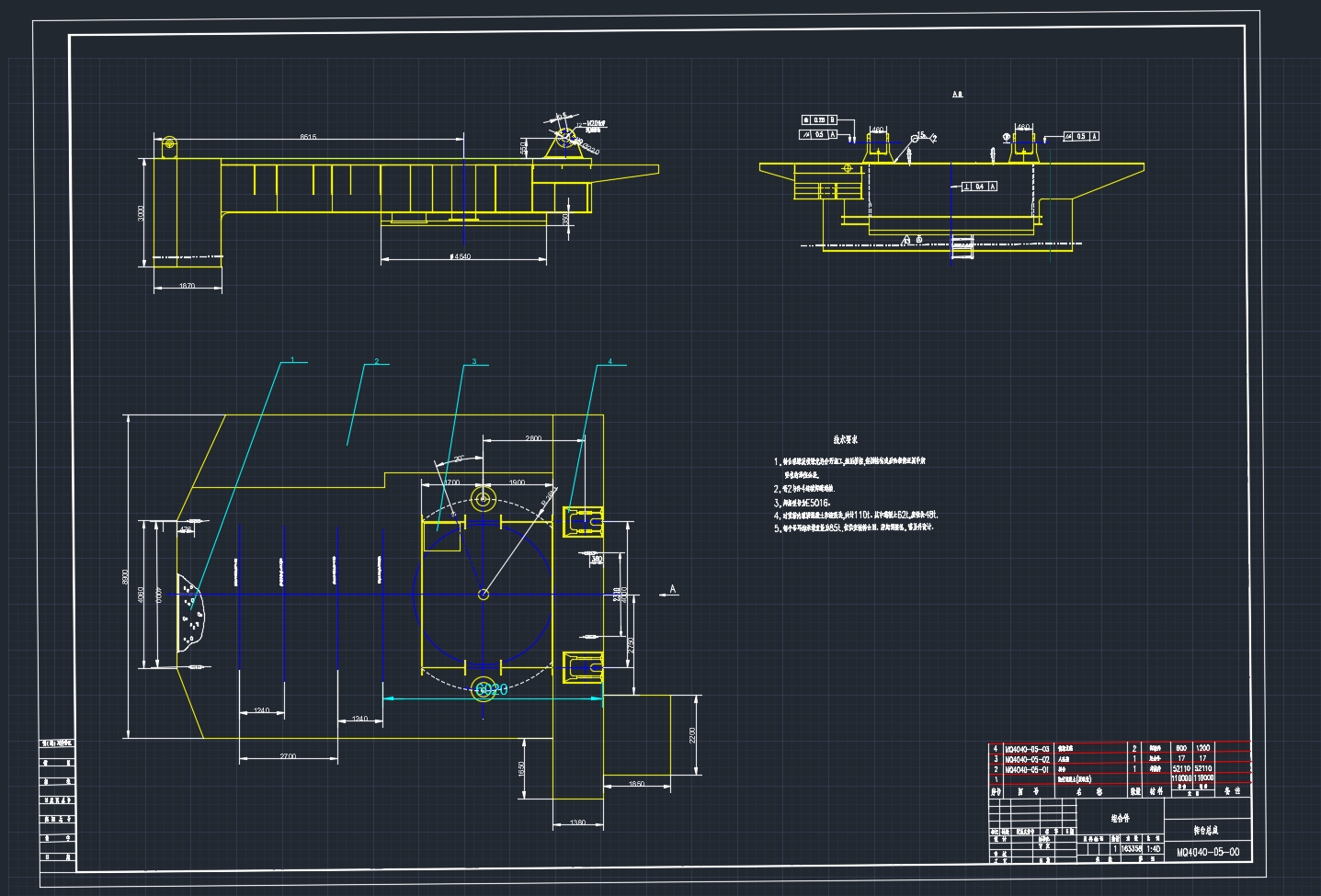
第3章转台结构总体设计计算 24
3.1 转台结构 24
3.2 转台的工作原理 24
3.3 转台结构的受力分析 24
3.4 转台强度、刚度校核 25
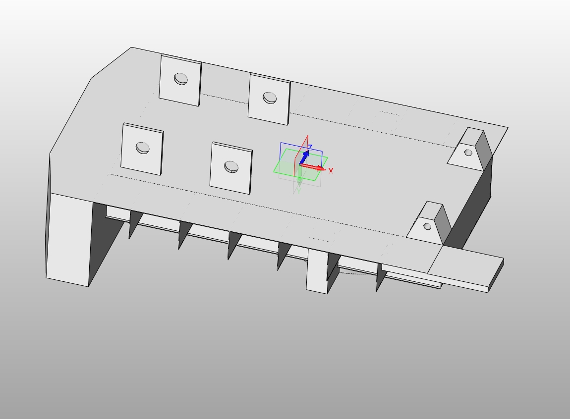
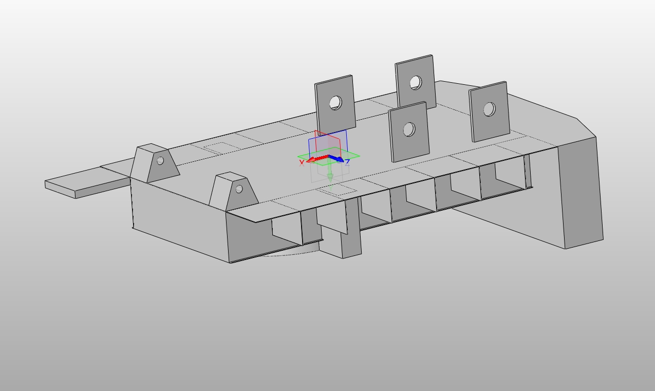
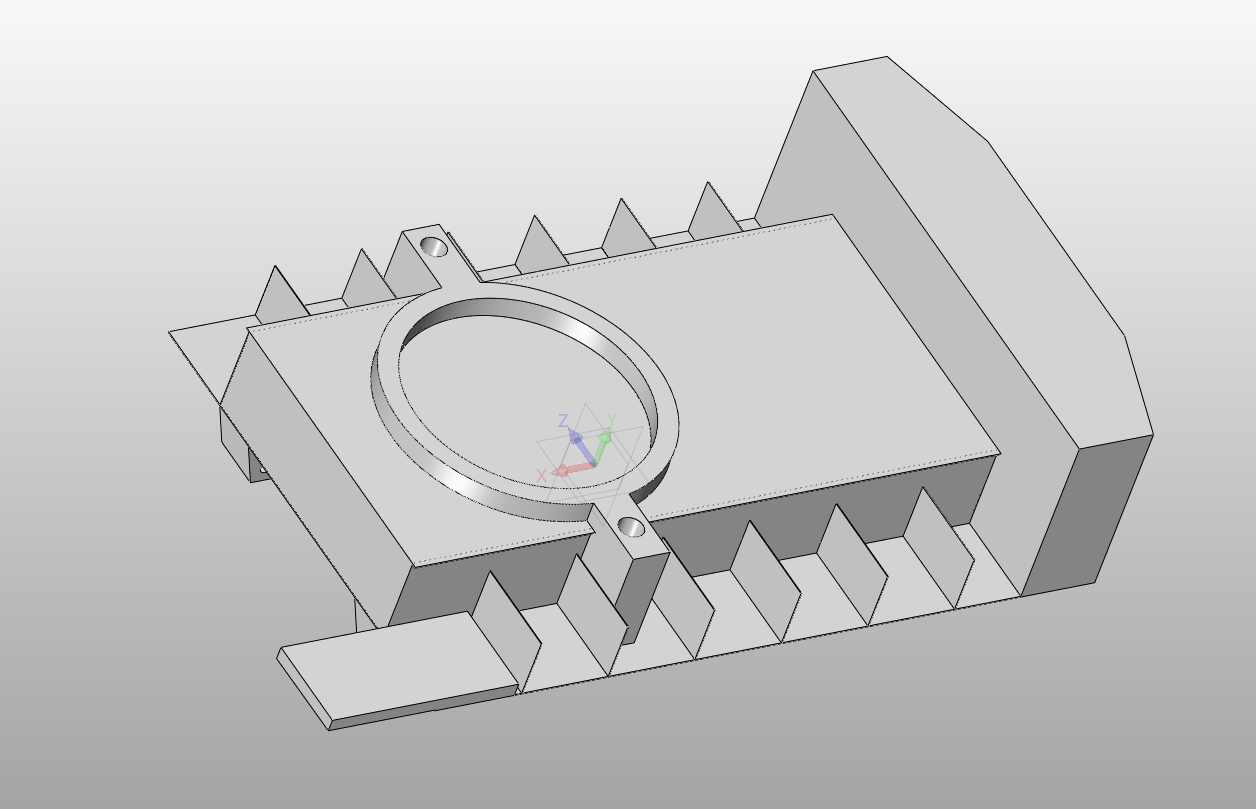
第4章转台结构三维建模和ANSYS分析 31
4.1 转台结构三维建模 31
4.2 转台结构ANSYS分析 32 [资料来源:www.doc163.com]
4.2.1 ANSYS软件简介 32
4.2.2 ANSYS有限元分析处理 32
4.2.3网格划分 33
4.2.4 载荷处理 33
4.2.5受力分析 35
第5章环境影响及经济型分析 36
5.1 环境影响分析 36
5.2 经济性分析 36
第6章结论 37
参考文献 38
致谢 40
下一篇:100m打桩船桩架变幅液压系统设计(含CAD零件装配图)