全长145.2m深茂铁路40+64+40m连续梁桥上部结构设计(含CAD图)

资料介绍:
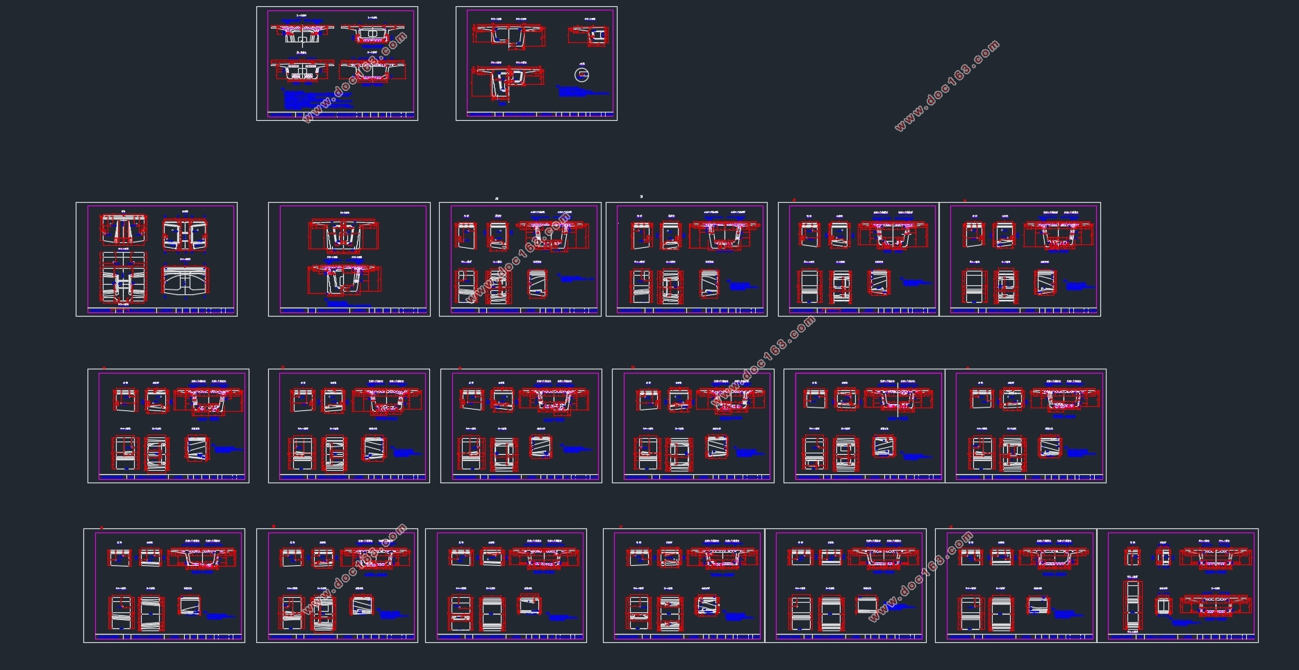
全长145.2m深茂铁路40+64+40m连续梁桥上部结构设计(含CAD图)(任务书,开题报告,论文说明书19000字,CAD图25张)
摘 要
这是一座铁路预应力混凝土连续梁桥,为双线铁路桥梁,主要设计桥梁的上部结构,设计荷载采用中-活载。
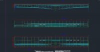
采用预应力混凝土连续梁桥,其桥跨布置为40+64+40m,全长为145.2m(含两侧梁端至边支座中心各0.6m)。主梁采用变高度变截面的单箱单室箱型截面,主梁的高度变化曲线采用半径为195.002m的圆曲线。桥面宽度为12.2m,中支座梁高5.2m,端部及中跨跨中梁高2.8m。主梁采用挂篮悬臂浇筑施工法,边跨现浇段采用满堂支架施工。
使用midas 软件进行建模分析,考虑施工过程体系转换和混凝土收缩徐变因素进行恒载内力计算。计算各控制截面内力影响线,并按最不利情况进行加载,求得活载内力包络图。根据各控制截面内力进行了估束和配筋计算,并绘制了梁体钢束布置图定义支座沉降组,按最不利组合求得支座沉降引起的最不利内力。依据规范选取截面系统温差模式,并计算温差引起的结构内力。分别按主力组合和主力附加力进行荷载组合,并得到结构组合内力包络图。最后,对各控制截面进行了强度、抗裂性、应力和变形验算,各项检算均满足铁路桥规对全预应力钢筋混凝土结构的要求。
[来源:http://Doc163.com]
关键词:连续梁;悬臂施工;内力计算;验算;midas
Abstract
This design is a prestressed concrete continuous beam bridge . It is a double line railway . The main job is to design the superstructure of the bridge. The load for design is the “ZK”live load.
A prestressed concrete continuous beam bridge with three spans of 40+64+40m was adopted. Its total span is 145.2m . First , the size of girder is determined;highly variable for the variable beam cross-section single-Box Single girder . And the box girder’s variation curve is a circular curve,which radiu is 195.002m.The bridge deck is 12.2m in width , the depth of beam at middle bridge seat is 5.2m ,and the depth of beam at mid-span is 2.8m .Balanced cantilever construction method is used in constructing main girder, and the cast-in-situ segment is constructed by full scaffold construction method.
Then the Midas program is used to calculate the internal force caused by dead load of the first stage considering the construction stage ,after imposing the second stage dead load on the complete system . The internal force of the stage is calculated . The internal force influence lines of the control section is calculated ,then the live load is imposed according to the most adverse circumstances to get the Force Envelope .According to the internal force of control sections the number of per-stressing steel stands is estimated and the per-stressing steel stands are arranged in the bridge .The program is used to determine the most adverse circumstances and calculate the internal force after defining the settlement groups of the basis.The temperature load is imposed consider the shrinkage and creep of the concrete . Then combination of load effects is made acoording to the Main force combination and the Main force plus additional force combination . Finally a check is made of the bearing capacity the ability to resist crack and the sterss of the control section ,all the requirements can be met .
[资料来源:http://www.doc163.com]
Keywords: Continuous beam; balanced cantilever construction; Internal force calculation; Checking computation; Midas
[来源:http://www.doc163.com]


[资料来源:http://doc163.com]
目录
摘 要 1
Abstract 1
目录 1
第1章 绪论 1
1.1预应力混凝土连续梁桥简述 1
1.2预应力混凝土连续梁桥施工方法 2
第2章 桥跨总体布置和结构主要尺寸 4
2.1 设计概述 4
2.2 截面尺寸拟定 4
2.2.1主梁梁高 4
2.2.2顶板和底板厚度 5
2.2.3腹板厚度 5
2.2.4横隔板 5
2.3 箱梁底缘曲线方程 6
2.4 构造特点 6
2.4.1 零号块 6
2.4.2 挂篮 6
2.4.3 合拢段 6
2.5 主梁分段 7
2.5.1 节段划分 7
2.5.2 计算图示 8
2.6 施工阶段划分 5
2.7 施工注意事项 5
第3章 结构内力计算 7
[来源:http://www.doc163.com]
3.1 恒载内力计算 7
3.1.1 材料特性 7
3.1.2 单元特性 8
3.1.3 施工荷载 8
3.1.4 二期恒载 8
3.1.5 计算模型 8
3.2 活载内力计算 12
3.2.1计算方法 12
3.2.2 活载动力系数的计算 12
第4章 预应力钢束设计 16
4.1 预应力钢束估算 16
4.1.1 计算原理 16
4.1.2 预应力钢束估算 21
4.2 纵向向预应力钢束布置 21
4.2.1 纵向预应力钢束的受力特点 21
4.2.2 纵向预应力钢束布置原则 22
4.2.3 纵向预应力钢束布置 23
第5章 截面特性计算 25
5.1 计算原理 25
5.1.1 净截面几何特性 25
5.1.2 换算截面几何特性 26
5.2 截面几何特性计算 27 [资料来源:http://doc163.com]
第6 章 预应力损失及有效应力 28
6.1 管道摩阻损失 28
6.2 锚具变形损失 29
6.3 混凝土弹性压缩损失 29
6.4 预应力钢筋应力松弛损失 29
6.5 混凝土的收缩徐变损失 30
6.6 有效预应力计算 31
6.7 关键截面预应力损失计算 31
第7章 次内力计算 33
7.1 预加力次内力计算 33
7.2 混凝土收缩次内力计算 35
7.3 混凝土徐变次内力计算 37
7.4 温度次内力计算 38
7.4.1 温度对结构的影响 38
7.4.2 结构温度场的确定 38
7.5 基础沉降次内力计算 40
第8章 内力组合计算 43
8.1 荷载的分类 43
8.2 荷载分项系数 43
8.3 主力组合 43
8.4 主力+附加力 45
[资料来源:http://Doc163.com]
第9章 主梁截面验算 47
9.1 强度验算 47
9.1.1 正截面强度验算 47
9.2 抗裂验算 49
9.2.1 正截面抗裂验算 49
9.3 应力验算 50
9.3.1 施工阶段应力 50
9.3.2 运营阶段应力验算 52
9.4 刚度验算 54
9.4.1 竖向挠度验算 54
参考文献 56
致 谢 57
[资料来源:Doc163.com]
上一篇:客家大桥(85+3×138+85m连续梁桥)上部结构设计(含CAD图,midas模型)
下一篇:全长177.3m深茂铁路48+80+48m连续梁桥上部结构设计(含CAD图,midas模型)
