(75+130+75m)I级公路预应力混凝土连续刚构桥设计(含CAD图)
(75+130+75m)I级公路预应力混凝土连续刚构桥设计(含CAD图)(任务书,开题报告,外文翻译,论文计算书18500字,CAD图纸24张)
摘 要
该次毕业设计旨在通过了解和分析有关资料对嘉陵江大桥进行上部结构的构造与分析,采用有限元分析软件Midas/Civil进行相关模型的建立和处理。通过对地质条件的勘测,拟定桥梁上部结构的尺寸,选择符合工程实际的材料类型,在兼顾单元划分的同时采用悬臂施工法模拟悬臂施工的步骤并建立模型。根据恒载及活载的相关荷载组合确定桥梁各施工阶段及使用阶段的内力值,以此为依据扩大15%进行截面配筋面积计算,初步估算钢筋数量。配筋结束后,通过PSC钢筋设计对各截面应力进行应力验算,通过调束,改变钢束形状、位置等手段保证各截面应力符合工程施工标准并且最大限度地发挥材料性能,最终确定在承载能力极限状态和正常使用极限状态下满足工程要求的桥梁模型。
关键词:连续刚构;应力组合;悬臂施工;有限元
Abstract
The graduation project is designed to analyze and understand the structure of the upper part of the Jialing River Bridge by means of understanding and analysis of the data.,using the finite element analysis software Midas/Civil to establish and deal with the related model. Through the survey of the geological conditions, draws up the dimensions of the upper structure of the bridge, with the type of material for the actual project, in both unit division and cantilever construction method is adopted to simulate cantilever construction steps and the establishment of the model. According to the relevant load combination of dead load and live load, the internal force value of each construction stage and the use of the bridge are determined. Based on this, the number of reinforcing steel bar is estimated, and the reinforcement area is calculated based on the expansion of 15%. After the end of the reinforcement, through the PSC reinforced design to the section stress of stress calculation, by adjusting the beam, change the steel beam shape, location, and other means to ensure that each section stress meet the engineering construction standards and maximize play performance materials, finally determined to satisfy the engineering requirements of the bridge model in the condition of bearing capacity limit state and serviceability limit state. [版权所有:http://DOC163.com]
Key Words:Continuous rigid frame;Stress Combination; Cantilever Construction;
Finite Element Analysis
2.1概述
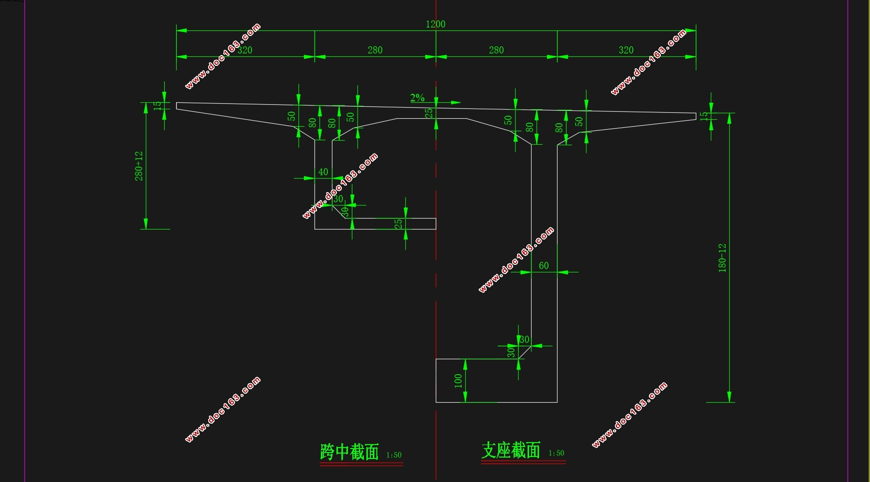
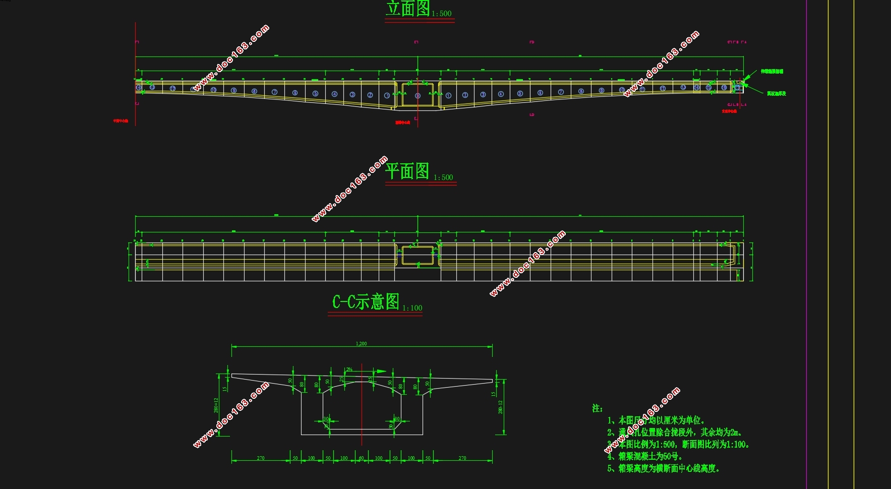
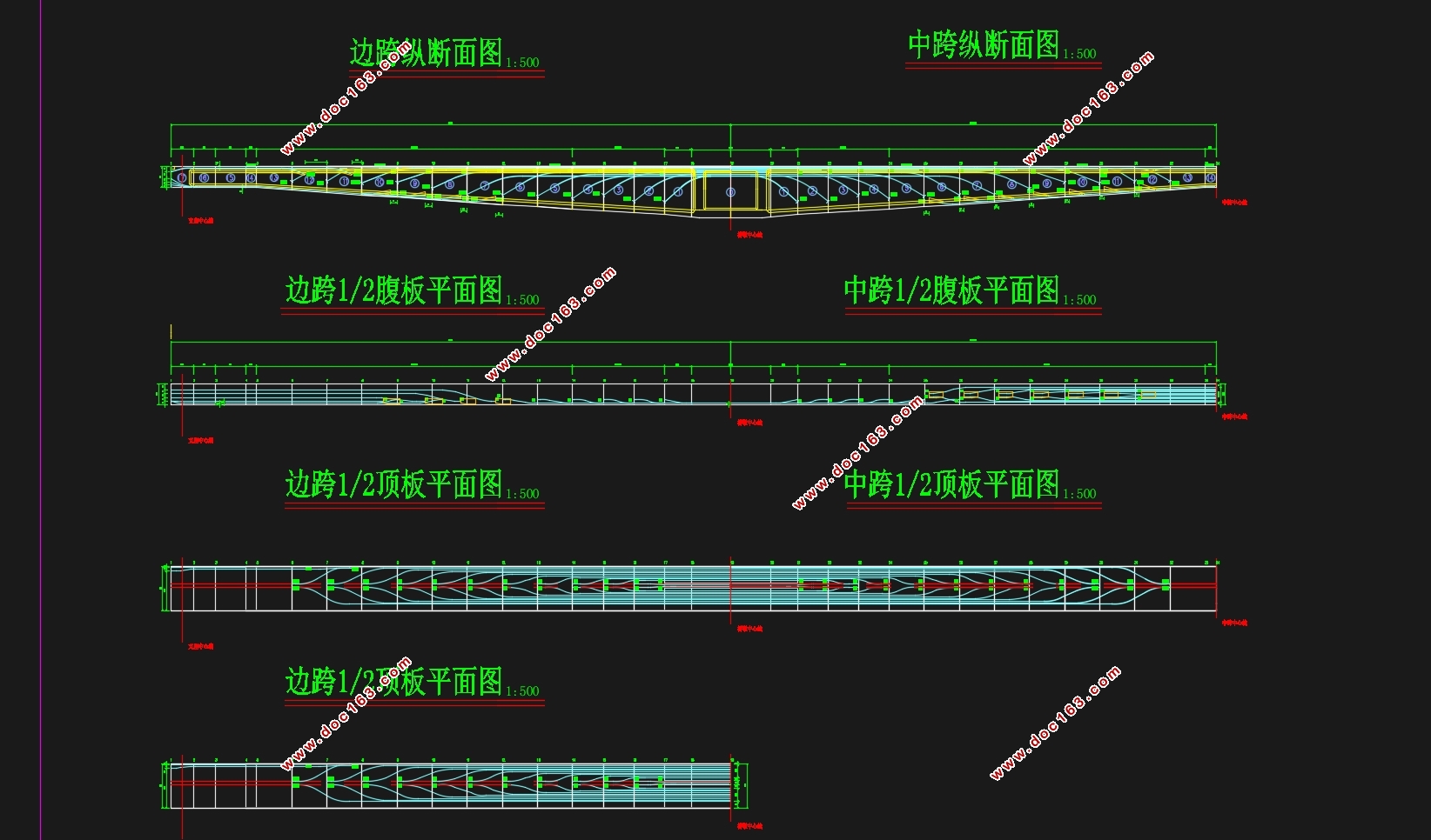
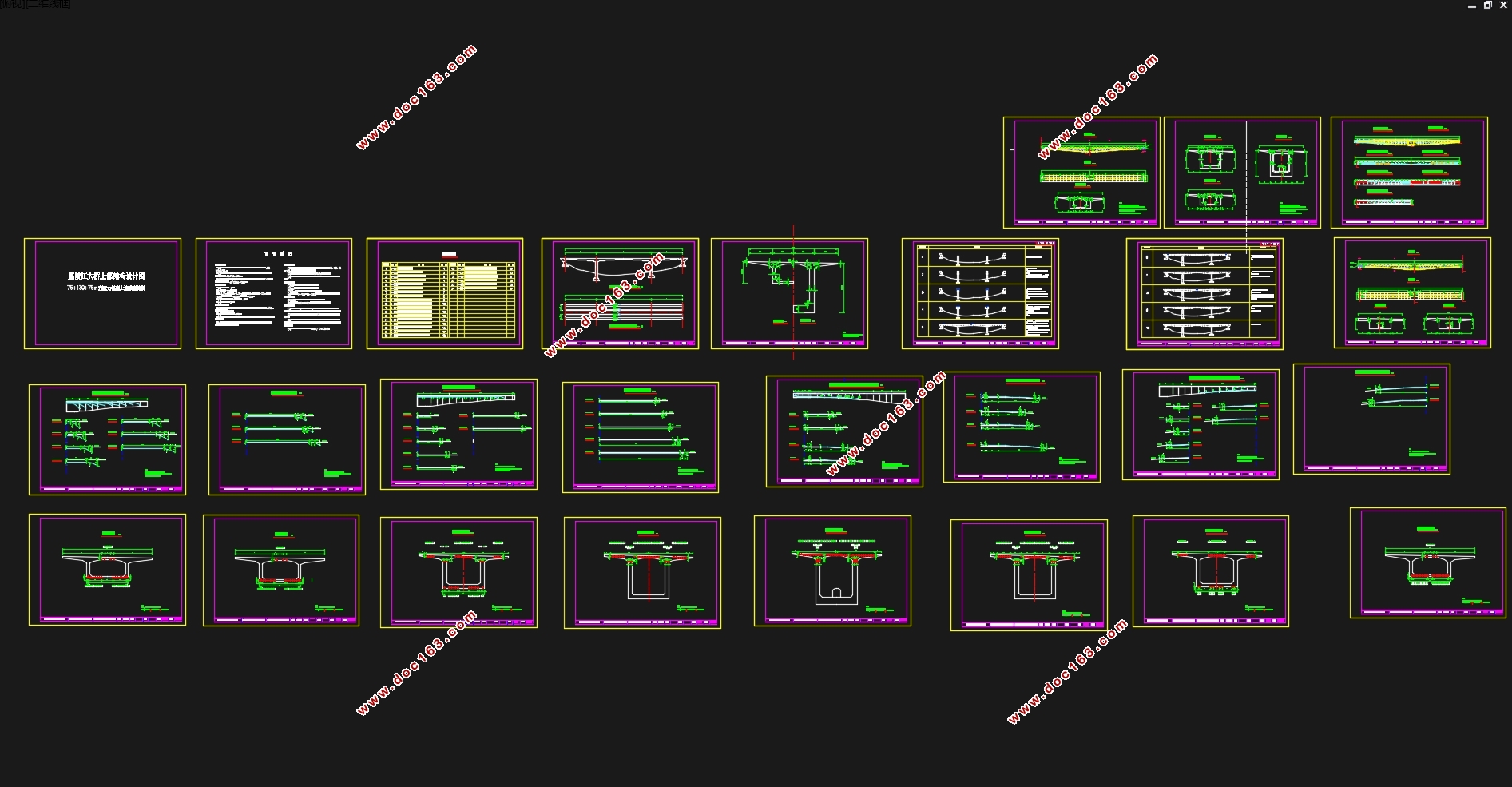
本次设计为I级公路预应力混凝土连续刚构桥,设计跨度75+130+75m,桥梁横向布置:0.5m(防撞护栏)+11.0m(车行道)+0.5m(防撞护栏),桥面纵坡0%,桥面横坡2%,桥轴平面线形为直线,下部结构采用双薄壁桥墩、肋板式桥台、天然扩大基础。
本设计主要采用单箱单室箱型截面,梁高沿纵桥线呈2次抛物线变化。中跨墩顶梁高6.5m,高跨比1/20;中跨跨中梁高2.8m,高跨比1/46.梁顶宽11.5m,底板宽5m;中跨墩顶处截面腹板厚80cm,中跨和边跨靠近边支座附近梁段腹板厚40cm。
[资料来源:http://www.doc163.com]

 [来源:http://www.doc163.com]

目 录
摘 要 I
第1章 绪论 1
1.1引言 1
1.2桥型的选择 1
1.2.1目的和意义 1
1.2.2基本内容和方法 1
1.2.3方案比选 3
1.3连续刚构桥简介 3
1.3.1总述 3
1.3.2连续刚构桥的基本构造 4
1.3.3连续刚构桥受力特点 4
1.3.4连续刚构桥的施工方法和特点 4 [来源:http://Doc163.com]
1.3.5连续刚构桥发展趋势 5
第2章 桥跨总体布置及结构尺寸拟定 7
2.1概述 7
2.2截面尺寸拟定 7
2.2.1孔跨布置 7
2.2.2变截面箱梁形式 7
2.2.3桥墩形式 7
2.2.4主梁高度 8
2.2.5顶底板厚度 8
2.2.6腹板厚度 8
2.3主梁分段与施工阶段划分 9
2.3.1悬臂施工阶段划分 9
2.3.2施工阶段划分 9
第3章 荷载内力计算 11
3.1结构混凝土毛截面特性计算 11
3.2恒载内力计算 11
3.3活载内力计算 14
3.3.1横向分布系数的考虑 14
3.3.2活载因子的计算 14
第4章 预应力刚束设计 17
4.1预应力钢束的估算 17
4.1.1正常使用极限状态验算 17
[资料来源:http://www.doc163.com]
4.1.2承载能力极限状态验算 18
4.1.3预应力钢束估算结果 19
4.2纵向预应力钢束布置 22
4.2.1纵向预应力钢束注意事项 22
4.2.2纵向预应力钢束布置原则 22
第5章 预应力损失与有效预应力计算 24
5.1预应力束与管道之间摩擦引起的预应力损失 24
5.2锚具变形、钢束回缩和接缝压缩引起的应力损失 24
5.3混凝土弹性压缩引起的应力损失 25
5.4钢束松弛引起的应力损失 26
5.5混凝土收缩徐变引起的应力损失 26
5.6有效预应力计算 27
第6章 次内力计算 30
6.1徐变次内力计算 30
6.1.1徐变次内力含义 30
6.1.2徐变次内力理论 30
6.1.3徐变变形对结构的影响 30
6.1.4先期恒载徐变次内力 30
6.1.5先期预应力徐变次内力 31
6.2温度次内力计算 32
6.2.1温度次内力的含义 32
6.2.2温度次内力理论 33
6.2.3等效荷载 34
6.3支座不均匀沉降次内力计算 35
6.3.1支座不均匀沉降次内力的含义 35
6.3.2支座不均匀沉降次内力理论 36
6.4预应力次内力计算 37
6.4.1预应力次内力的含义 37
6.4.2预应力次内力理论 37
第7章 截面验算 39
7.1内力组合 39
7.1.1 作用与作用效应 39
7.1.2 内力组合 39
7.2截面验算 40
7.2.1承载能力极限状态验算 40
7.2.2正常使用极限状态验算 43
7.3持久状况预应力混凝土构件应力验算 49
7.3.1使用阶段正截面压应力验算 49
7.3.2使用阶段斜截面压应力验算 52
7.3.3施工阶段正截面法向应力计算 54
7.3.4受拉区钢筋的拉应力验算 56
第8章 主要工程数量计算 59
参考文献 60
致谢 61
[资料来源:http://www.doc163.com]
