
凸轮轴磨床的结构及控制系统设计(含CAD零件装配图,电路图)
凸轮轴磨床的结构及控制系统设计(含CAD零件装配图,电路图)(任务书,开题报告,论文说明书14000字,电路图,CAD图6张)
摘 要
凸轮轴已经成为汽车发动机配气机构中的最为重要的部分,其加工精度直接影响着发动机整体性能。因此,通过分析国内外凸轮轴磨床、磨削技术以及数控系统的研究,开展对凸轮轴数控磨床的机械结构及数控系统的研究,本文介绍了凸轮轴数控磨床主要机械结构设计及西门840D系统在数控磨床上的应用。通过对凸轮轴工件加工工艺进行分析,对磨床进行了主轴系统的结构设计和控制电路软硬件设计。
通过对凸轮轴加工要求分析其对数控磨床的功能需求以及生产线正常加工时的动作流程,根据分析控制系统性能需求,凸轮轴磨床控制系统采用PC嵌入NC结构,选用西门子SINUMERIK 840D数控系统作为主控单元。设计机床控制电路、伺服控制和系统配置等,完成曲轴磨床实验平台的搭建。
关键词:凸轮轴;数控磨床;结构设计;控制电路设计
Abstract
As the key part of the automobile engine valve train, the performance of the cam shaft directly affects the whole performance of the engine. In view of the above questions, in the analysis of the cam at home and abroad of grinding axis the latest research development and application based on, to carry out the core components of high speed and high precision CBN cam shaft grinding machine, static pressure bearing electric spindle, linear motor of the grinding wheel frame of the research work, the CNC system adopts Siemens CNC system 840D. This paper introduces the application of NC camshaft grinder mainly mechanical structure design and Simon 840D system in CNC grinder. In this paper, the processing technology of camshaft workpiece is analyzed, and the structure design of the main spindle system of the grinder and the design of the hardware and software of the control circuit are also analyzed.
[资料来源:http://www.doc163.com]
Analysis of the functional requirements of CNC grinding machine and production line normal processing flow of action by the camshaft machining requirements, according to the analysis of control system performance requirements, cam shaft grinding machine control system using PC embedded NC structure, selection of Siemens SINUMERIK 840D CNC system as the main control unit. Design the control circuit, servo control and system configuration of the machine tool, and complete the experiment platform of the crankshaft grinding machine.
Key Words:Cam shaft; NC grinder; structure design; control circuit design
凸轮轴是较为常见的非圆类磨削工件,在磨削过程中,需要多参数的输入和输出,且数据之间为非线性映射关系,使得工件的加工质量很难保证。因此,通过分析凸轮轴磨削工艺特点,设计合理的磨床系统,提高零件的加工精度显得尤为重要。
凸轮轴数控磨削加工原理
目前,对于凸轮轴等非圆轮廓表面的磨削基本上都选用数控磨床来进行加工。这种加工方式与传统的靠模仿型相比,X-C轴联动的数控磨床加工方式能过大幅度的提高加工效率和精度,同时也具有更高的柔性。 [版权所有:http://DOC163.com]
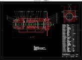
其加工原理图如图2.1所示,加工时,由工作人员编写的数控指令来控制C轴的旋转,Z轴滚珠丝杠的旋转以及X轴直线电机的进给运动。在工件旋转固定的角度后,X轴直线电机工作,带动砂轮架做往复运动,数控系统自动运算出各轴的移动量,使得X轴、C轴联动完成一个凸轮轴外形的加工。然后Z轴丝杠驱动工作台,使工件移动到下一个凸轮的加工地方。
[来源:http://Doc163.com]


[资料来源:Doc163.com]

目录
第1章绪论 1
1.1研究背景 1
1.2国内外研究现状 2
1.2.1凸轮轴磨削技术 2
1.2.2数控系统 3
1.3本文研究内容 4
第2章凸轮轴磨床的设计 6
2.1凸轮轴数控磨削加工原理 6
2.2 凸轮轴磨削控制系统需求 7
2.3 西门子840D系统的功能与结构 7
2.4本章小结 9
第3章砂轮架关键部件结构设计 10
3.1主轴系统设计 10
3.1.1主轴的设计及计算 10
3.1.2电主轴 12
3.1.3 液压静压轴承 12
3.2 CBN砂轮 13
3.3本章小结 13
第4章磨床控制系统硬件设计 14
4.1 机床控制电路总体设计 14
4.2伺服驱动设计 16
4.2.1 伺服驱动单元电路配制 16
4.2.2 电机编码器选型 17
4.3 控制电路及I/O接口 19
4.4本章小结 21
第5章磨床控制系统软件设计 22
5.1 NC系统设置 22
5.2 PLC软件编程 23
5.2.1硬件组态 24
5.2.2 PLC软件程序 25
5.3本章小结 27
参考文献 28
致谢 29
附录 30
上一篇:基于机械臂结构的3D打印机虚拟样机设计(SolidWorks三维,ADAMS仿真)
下一篇:单笼货运施工电梯附墙架、架底安全护栏及电气系统的设计(含CAD图)