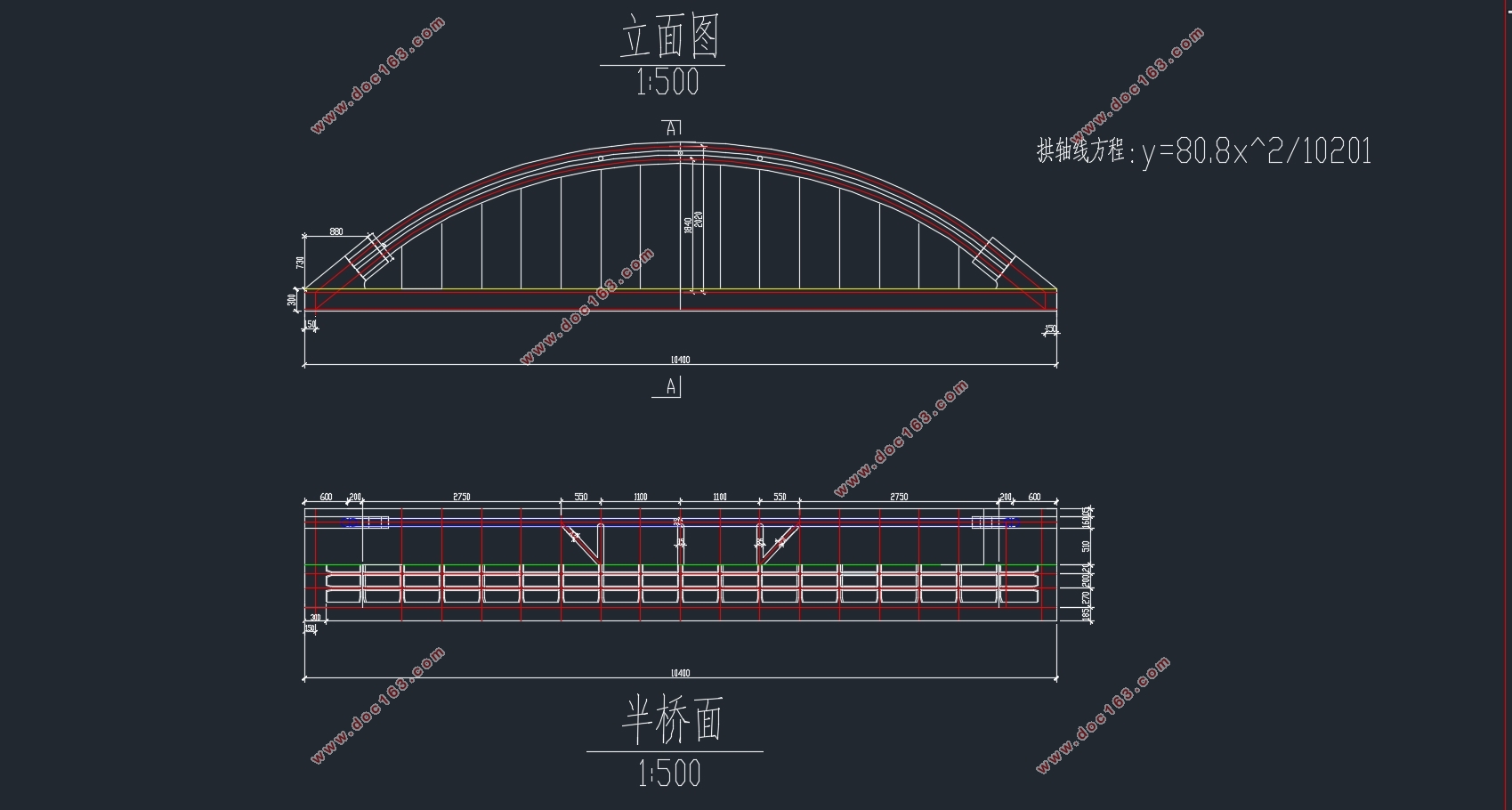
苗家坪大理河104m跨铁路桥设计(含CAD图)

苗家坪大理河104m跨铁路桥设计(含CAD图)(论文说明书13000字,CAD图16张)
摘要
本次设计的对象是苗家坪大理河跨铁路桥,采用钢管混凝土系杆拱桥,跨径为104m,系梁高为3m 在端部加强,横梁高为 2.2m。
钢管混凝土拱桥是我国近年来桥梁建筑发展的新技术, 具有自重轻、 强度大、抗变形能力强的优点。它较好地综合满足了修建桥梁所需求的用料省、安装重量轻、施工简便、承重能力大的诸多要求,是大跨度拱桥的一种比较理想的结构形式。
本设计根据任务书要求设计一下承式钢管混凝土拱桥。下承式钢管混凝土拱桥美观且受力合理, 但该种桥型设计参数较多, 各参数相互关联, 给设计工作带来了困难。
首先进行初步设计,即拟定所选方案桥型的具体尺寸以及相关参数。第二步就要进行结构计算,这其中最为关键的便是建模,最后的计算是否正确,在很大程度上取决于模型建得是否正确。本设计利用MIDAS软件计算,将建好的模型图导入软件,并将计算好的模型参数赋给模型结构单元。添加约束后模型就宣告建立完成,进入计算阶段。利用软件就可计算出结构各控制截面的内力。
完成上述工作后,便要进行结构验算,对于拱桥最重要的就是要验算拱圈截面承载力与拱圈的整体稳定性。
[版权所有:http://DOC163.com]
Abstract
The content of the present desigen is on the miaojiaping Bridge. whichadopts the formof concrete-filled steel tube tied arch bridge. The span arrangement is104m. The height ofthe tie girder on the support is3m,and the height of beam is2.2m.
Concrete filled steel tube arch bridge is a new technology in the development of bridge construction in recent years in our country, it has the advantage of light deadweight, intensity big, the advantages of resistance to deformation ability. It integrated well meet the demand of the Bridges are the materials, installation, light weight, convenient construction, large bearing capacity of requirements, is a kind of ideal of long-span arch bridge structure.
This design according to the specification requirements to design a concrete-filled steel tube concrete arch bridge. Concrete-filled steel tube concrete arch bridge is beautiful and reasonable force, but this kind of bridge design parameters is more, the parameters related, brought difficulties to design work.
First carries on the preliminary design, the size for the selected scheme of bridge and the related parameters. The second step is to structure calculation. That is one of the most critical modeling, the final calculation is correct, to a large extent depends on the model built is correct. This design using MIDAS software, good model diagram will be built into the software, and calculates the good model parameter is assigned to model structure unit. Add constraint model was set up after the completion, entered into the phase of computing. Using the software can calculate the structure internal force of the control section.
Completion of work, the structure and checking calculation of will, the most important thing is to check for arch bridge bearing capacity of arch ring cross section and the overall stability of arch ring.
[资料来源:https://www.doc163.com]


目录
摘要 I
第一章 工程概况 1
1.1工程背景 1
1.2系杆拱桥的发展 2
1.3系杆拱桥的承载特点 2
1.4系杆拱桥的结构特征和结构组成 4
1.5主要技术标准和设计基础资料 8
第二章 钢管混凝土拱桥方案设计 10
2.1.主拱圈设计 10
2.2横撑构造 11
2.3主梁构造 12
2.4.吊杆构造 12
2.5横梁构造 13
2.6纵梁构造 14
2.7桥墩方案设计 16
2.8方案比较 17
第三章 设计荷载及荷载组合 18
3.1恒载 18
3.2活载 18
3.3 附加力 18
3.4荷载组合 21
第四章 内力计算 22
4.1单元划分 22
4.2边界条件 22
4.3索力调整 23
4.4拱肋内力计算 23
4.4.1拱肋截面尺寸特性 23
4.4.2拱肋内力图 24
4.5钢管混凝土拱肋应力计算 30
4.6横撑,斜撑内力 33
4.7吊杆内力计算 33
[资料来源:Doc163.com]
4.8主梁内力及应力计算 34
4.9主梁应力 37
第五章 预应力钢束及普通钢筋的计算和布置 38
5.1预应力钢束计算布置 38
5.2预应力损失及有效预应力计算 39
5.3普通钢筋的计算及布置 39
5.3.1主梁 39
5.3.2横梁 41
5.3.3纵梁 42
第六章 构件验算 43
6.1主拱承载能力极限状态验算 43
6.2钢管混凝土拱肋应力验算 47
6.3横撑,斜撑强度验算 47
6.4吊杆强度验算 47
6.5主梁应力验算 47
6.6拱肋面内稳定验算 48
6.6.1 稳定系数 49
6.6.2偏心率折减系数 49
6.6.3混凝徐变折减系数 50
6.6.4稳定承载力 50
6.7正常使用极限状态计算 51
6.7.1主梁正截面抗裂验算 51
6.7.2主梁斜截面抗裂验算 52
6.8承载能力极限状态验算 53
6.8.1主梁轴心受拉正截面承载力验算 53
6.8.2主梁斜截面承载力计算 53
参考文献 55
致谢 56
上一篇:4×30m预应力混凝土先简支后结构连续箱梁桥施工图设计(含CAD图)
下一篇:78+120+78m预应力混凝土连续梁桥主跨桥设计(含CAD图)
