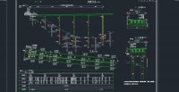
湖北恩施先简支后连续预应力混凝土T梁桥设计(含CAD图)

湖北恩施先简支后连续预应力混凝土T梁桥设计(含CAD图)(任务书,开题报告,论文说明书26000字,CAD图25张)
摘 要
连续梁桥这种桥型在工程上应用广泛,它不仅具有非常高的强度,刚度及抗裂性能,还具有行车平顺稳定,需要后期养护量少,设计方案较完善及施工经验较成熟的特点。设计施工一座连续梁桥必须从桥址的选择,桥跨度布设,截面尺寸的拟定,梁预应力钢束布置以及施工技术等方面综合考虑,还必须考虑当地环境的影响。
本次毕业设计为5 40m预应力混凝土连续T梁桥,桥宽12m,梁高2.5m。桥面设50cm(防撞墙)+1100cm(行车道)+50cm(防撞墙)。荷载等级为公路—I级。梁断面为5片T梁截面。主梁采用先工厂预制再吊装成桥的施工方法。计算分析利用结构力学知识,并利用Midas Civil对手算结果进行验算。
进行桥梁上部结构和下部结构的设计和计算,上部结构的设计和计算主要是指主梁的设计和计算;下部结构的设计和计算包括盖梁的设计与计算,桥台的设计与计算,墩柱的设计与计算以及桩基的设计与计算。
关键词:连续梁桥、预应力、先简支后连续、上部结构、下部结构
Abstract
The continuous beam bridge is a kind of bridge type used widely on the project. It not only has a reliable strength, stiffness and cracking, but also has a smooth journey comfortable, conservation work on the design and construction experience of the characteristics of maturity. Design a bridge must be laid across from the bridge-laying, the size of the development, steel beam layout and construction methods, but also give full consideration to the design parameters and environmental impact. [资料来源:www.doc163.com]
This graduation design uses 5 40 m other sections of prestressed concrete continuous T beam bridge design, bridge width of 12m, beam of high 2.5m. Bridge design 0.5 m (Crash barriersr)+11m (Lane)+0.5m (Crash barriersr). Load rating of highway-I level. Beam cross section as a five piece T beam sectional. Construction method of Prefabricated lifting is adopted in this bridge construction. Structure calculation and analysis under the plane force system, and using Midas checking software on the calculation results.
The second step is to design and calculate both upside structure and lower part structure .The design and calculation of upside structure mainly includes main girder ; the design and calculation of lower part structure includes Abutment, Cap girder, Pier column, and Pile foundation.
Keywords : Continuous beam bridge;Prestress;Simple Support and Continuous;Upside structure; Lower part structure
设计内容
本次设计是湖北省恩施石板溪大桥引桥部分,上部结构构造为 m预应力混凝土连续T梁,简支转连续结构体系。40mT梁预制梁的高度为2500mm,半幅桥每跨布置5片T形截面梁,梁的间隔距离2400mm。T梁利用后张法浇筑,工厂场预制后吊装成桥。桥面净宽度为11m(两边各去除50cm防撞护栏),每幅单行行驶,布置三个车道。
[来源:http://Doc163.com]
[来源:http://Doc163.com]


目 录
摘 要 I
Abstract II
第1章 绪 论 1
1.1概述 1
1.2毕业设计的目的与意义 2
第2章 设计的基本资料 3 [来源:http://www.doc163.com]
2.1 设计内容 3
2.2 其他资料 3
第3章 桥梁主要材料与截面特性 4
3.1 桥梁线性布置 4
3.2技术标准与设计规范 4
3.3技术指标 4
3.4主要材料 5
3.5 设计要点及结构尺寸拟定 6
3.5.1 设计要点 6
3.5.2结构截面尺寸拟定 7
3.5.3横截面沿跨长的变化 10
3.5.4横隔梁的设置 10
3.5.5毛截面几何特性计算 10
第4章 主梁内力计算 13
4.1结构自重作用效应计算 13
4.1.1 结构自重作用荷载集度计算 14
4.1.2 内力计算 14
4.2 汽车荷载作用效应计算(边梁) 19
4.2.1 冲击系数和车道折减系数 19
4.2.2计算主梁的荷载横向分布系数 20
4.2.3 汽车荷载效应内力计算 25
[资料来源:Doc163.com]
4.3基础沉降计算 32
4.4内力组合 35
4.4.1按承载能力极限状态设计 35
4.4.2按正常使用极限状态设计 35
4.4.3 计算结果 36
第5章 预应力钢束的估算及布置 39
5.1钢束估算 39
5.2 钢束布置 41
5.2.1 钢束布置构造要求 41
5.2.2 钢束布置原则 41
5.2.3 钢束起弯角和线型的确定 42
5.3主梁净截面及换算截面几何特性 44
第6章 非预应力钢筋的估算与布置 47
6.1负弯矩非预应力钢筋的计算 47
6.2箍筋计算 47
第7章 预应力损失及有效预应力计算 49
7.1基本理论 49
7.2 预应力损失计算 49
7.2.1 预应力钢筋与管道之间摩擦引起的应力损失 49
7.2.2后张法锚具变形、钢筋回缩和接缝压缩引起的应力损失 52
7.2.3后张法由混凝土弹性压缩引起的应力损失 55
7.2.4后张法由钢筋松弛引起的预应力损失终极值 56
7.2.5后张法由混凝土收缩、徐变引起的预应力损失 57
7.2.6 截面预应力损失合计和有效预应力 58
第8章 Midas建模验算 59
8.1 Midas建模过程 59
8.2 Midas分析过程 69
8.3 Midas验算 73
8.3.1验算正截面抗弯承载能力 73
8.3.2 使用阶段正截面压应力验算 77
8.3.3 使用阶段斜截面主压应力验算 80
第9章 盖梁的设计与计算 84
9.1盖梁自重及内力计算 84
9.2 盖梁活载计算 84
9.3 内力组合 86
9.4内力计算 86
9.5 配筋计算 86
9.6 抗裂验算 87
第10章 墩柱的设计与计算 89
10.1 荷载计算 89 [资料来源:www.doc163.com]
10.1.1 恒载计算 89
10.1.2 活载计算 89
10.2 截面配筋计算及应力验算 90
第11章 钻孔灌注桩计算 93
11.1 荷载计算 93
11.2 桩长计算 93
11.3 桩的内力及位移计算 95
11.4 桩顶纵向水平位移验算 98
11.5 桩基配筋计算及桩身材料截面强度验算 99
第12章 桥台设计 101
12.1 桥台类型和主要材料 101
12.2 桥台一般构造尺寸的拟定 101
12.3 台帽计算 102
12.3.1荷载计算 102
12.3.2内力计算 103
12.3.3截面验算 103
12.4 台墙计算 104
12.4.1垂直荷载计算 104
12.4.2水平力计算 105
12.4.3钢筋配置 107
12.5 地基承载力验算 108
[来源:http://Doc163.com]
参考文献 110
致 谢 112
[版权所有:http://DOC163.com]
上一篇:钢桁架桥的疲劳验算
