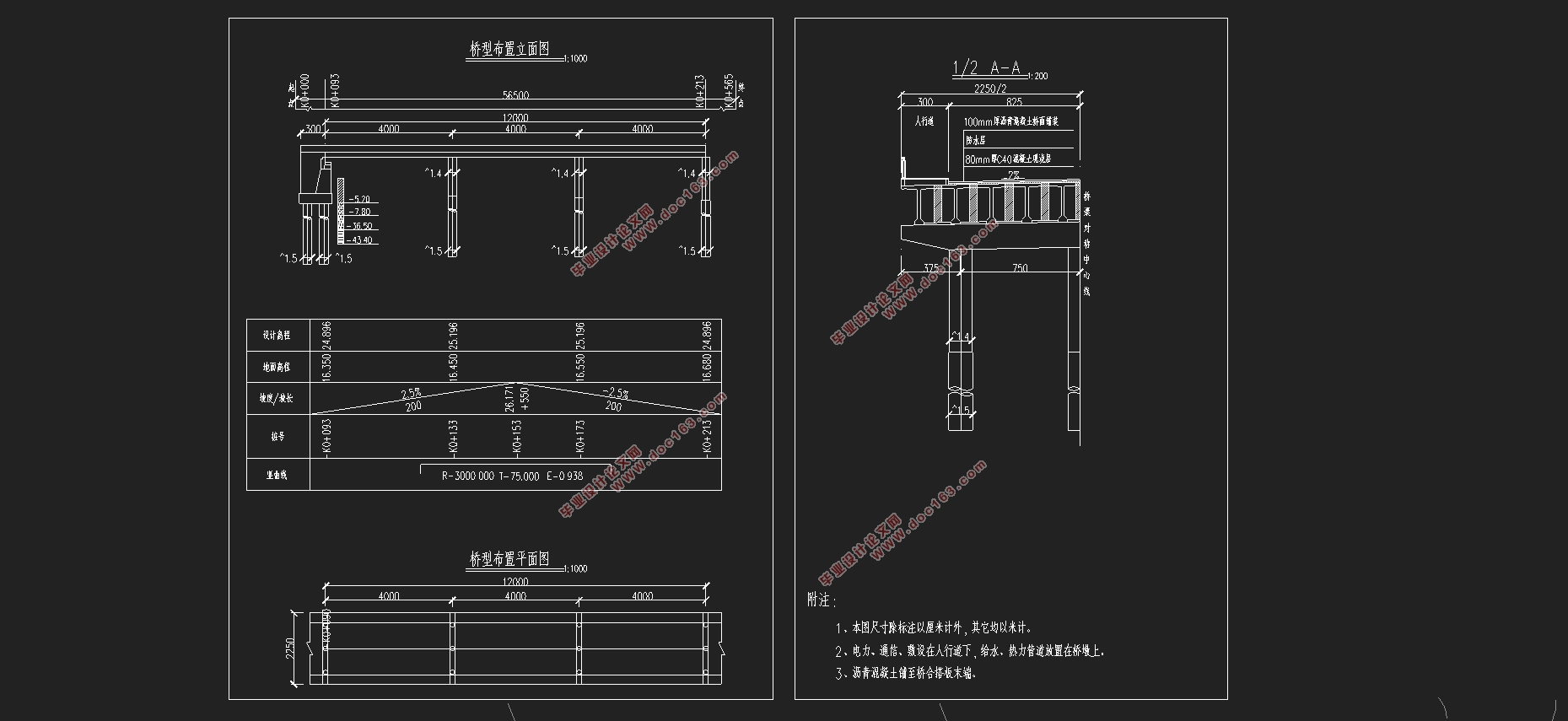
3×40m预应力混凝土先简支后结构连续T形梁桥部分结构设计(含CAD图)

3×40m预应力混凝土先简支后结构连续T形梁桥部分结构设计(含CAD图)(任务书,开题报告,外文翻译,论文计算书22000字,CAD图24张)
摘 要
本次毕业设计的题目是3×40m 计,该设计以新汴河虞姬大桥中实际项目为背景,属于该项目引桥的第一联的 和 。 T梁的特点。因此 T梁桥常用于 制,本次毕业设计没有对横向预应力、竖向预应力以及抗震进行设计。
本次设计大致分为两个过程。首先是根据规范和设计经验拟定 和 的主要构造和相关细部的尺寸,考虑到桥梁结构形式与地质条件,桥台的设计采用肋板台,桥墩的设计选用圆柱墩,基础的设计均选用摩擦桩。施工方式确定为预制吊装施工。
第二个过程是运用MIDAS软件对上部结构进行计算分析,包含对配筋结果的计算,对内力的分析,进行施工阶段及正常使用阶段的各项截面验算。同时要考虑到混凝土收缩徐变、地基不均匀沉降、整体及局部温差所产生的次内力等因素的影响。行车道板验算、锚下局部承压验算与下部结构设计均采用手算的方式,下部结构主要对桥墩、桥台以及桩基础进行设计与计算。
从MIDAS最终分析可知本桥梁在施工阶段以及使用阶段的各项验算均能通过,说明本次设计桥梁内力的分布情况合理,并满足相关的规范要求。 [资料来源:www.doc163.com]
关键词:先简支后转结构连续;T梁桥;结构分析:MIDAS/CIVIL
Abstract
The title of the graduation design is the design of the 3×40m prestressed concrete first simple supported continuous T beam bridge construction drawing design. This design takes the actual project of the Yuji bridge in the new Bian River as the background, and belongs to the first superstructure and substructure of the project's lead bridge. Simple construction, strong seismic capacity, smooth and comfortable driving, easy maintenance and so on are the characteristics of prestressed concrete continuous T beams.Therefore, prestressed concrete T beam bridge is commonly used in medium and small span bridges.Due to the time constraint, the design of transverse prestressing, vertical prestressing and aseismic design has not been carried out in this graduation project.
This design is roughly divided into two processes. First, according to the standard and design experience, the main structure of the upper structure and substructure and the size of the related details are drawn up. Considering the structure and geological conditions of the bridge, the design of the abutment adopts the ribs, the pier is designed to choose the pier, and the friction pile is selected for the basic design. The construction method is determined as prefabricated hoisting construction.
[来源:http://www.doc163.com]
The second process is to use MIDAS software to calculate and analyze the superstructure, including the calculation of reinforcement results, internal force analysis, and the cross section checking of the construction stage and the normal use stage. At the same time, we should take into account the factors such as shrinkage and creep of concrete, uneven settlement of foundation, and secondary internal forces generated by the overall and local temperature difference. The checking calculation of the roadway board, the checking calculation of the local anchorage under the anchor and the design of the substructure are all calculated by hand, and the lower structure is mainly designed and calculated for the pier, abutment and pile foundation.
Finally, the MIDAS analysis shows that the bridge's checking in the construction and use stage can be passed, which shows that the design of the bridge is reasonable in internal force distribution and meets the requirements of the corresponding specifications.
Key words:simple post-continuous combination beam bridge; T beam bridge ;structural analysis; MIDAS/CIVIL [资料来源:http://Doc163.com]
[资料来源:https://www.doc163.com]


目录
第1章 绪论 1
1.1预应力混凝土连续梁桥的发展概述 1
1.2选题设计思想及意义 1
第2章 桥型方案比选 2
2.1构思宗旨 2
2.2比选原则 2
2.3设计方案 2
2.3.1预应力混凝土先简支后结构连续T型梁桥 2
2.3.2装配式预应力混凝土简支T型梁桥 2
2.3.3预应力混凝土变高度连续箱梁桥 3
第3章 桥跨总体布置及结构尺寸拟定 5
3.1桥跨布置 5
3.2上部结构尺寸拟定 5
3.2.1顺桥向主梁尺寸拟定 5
3.2.2横桥向主梁尺寸拟定 5
3.3下部结构尺寸拟定 5
3.3.1墩身尺寸拟定 5
3.3.2桥台拟定 5
3.3.3桩基础尺寸拟定 6
第4章 建模 7
4.1模型简化 7
4.1.1横向分布系数的计算 7 [资料来源:http://Doc163.com]
4.1.2模型简化 8
4.2主要参数说明 8
4.2.1材料参数 8
4.2.2荷载参数 9
4.2.3边界说明 10
4.3施工阶段说明 10
第5章 桥梁结构内力计算 11
5.1恒载内力 11
5.2活载内力 17
第6章 预应力钢筋设计及预应力损失计算 22
6.1预应力钢筋设计 23
6.1.1纵向预应力筋估算 23
6.1.2 预应力筋的布置 29
6.2 预应力损失 30
6.2.1预应力钢筋与管道壁之间的摩擦σl1 30
6.2.2锚具变形、钢筋回缩和接缝压缩σl2 30
6.2.3预应力钢筋与台座之间的温差σl3 31
6.2.4混凝土的弹性压缩σl4 31
6.2.5预应力钢筋的应力松驰σl5 31
6.2.6混凝土的收缩徐变σl6 31 [来源:http://Doc163.com]
6.2.7 预应力损失计算结果 32
第7章 次内力计算及内力组合 35
7.1温度次内力 35
7.1.1计算依据及方法 35
7.1.2温度次内力计算结果 35
7.2基础不均匀沉降次内力 41
7.3预应力次内力 44
7.4收缩次内力 46
7.5徐变次内力 49
7.6内力组合 51
7.6.2正常使用极限状态组合 54
第8章 主要截面验算 58
8.1承载能力极限状态截面验算 58
8.1.1正截面抗弯验算 58
8.1.2斜截面抗剪验算 62
8.2正常使用极限状态截面验算 63
8.2.1使用阶段正截面抗裂验算 64
8.2.2使用阶段斜截面抗裂验算 66
8.2.3挠度验算 69
8.3持久状况和短暂状况构件的应力验算 69
8.3.1使用阶段正截面压应力验算 70 [资料来源:http://www.doc163.com]
8.3.2使用阶段斜截面主压应力验算 72
8.3.3施工阶段正截面法向应力验算 74
8.3.4受拉区钢筋的拉应力验算 78
第9章 锚下局部承压验算 80
9.1局部受压区尺寸要求 80
9.2局部抗压承载力计算 81
第10章 行车道板计算 82
10.1中间单向板计算 82
10.1.1恒载内力 82
10.1.2活载内力 82
10.2外边梁悬臂板内力计算 83
10.2.1恒载内力 83
10.2.2活载内力 83
10.3荷载组合 83
10.3.1连续板 83
10.3.2悬臂板 84
10.3桥面板配筋 84
10.3.1桥面板配筋 84
10.3.2抗剪验算 85
第11章 桥墩计算 86
11.1荷载计算 86
11.2截面配筋计算 87
11.3墩柱截面承载力验算 88
第12章 桥墩钻孔灌注桩计算 89
12.1荷载计算 89
12.2桩长计算 89
12.3桩的内力及位移计算 90
12.3.1基本假定 90
12.3.2桩的计算宽度 90
12.3.4桩的变形系数 91
12.3.5桩身最大弯矩位置及弯矩计算 91
12.3.6计算最大冲刷线下深度Z处桩截面上的弯矩 及水平压应力 91
12.3.7桩顶纵向水平位移验算 92
12.4桩身截面配筋计算 93
12.5桩截面承载力验算 94
第13章 桥台计算 96
13.1盖梁计算 96
13.1.1计算模型 96
13.1.2盖梁截面配筋 97
13.1.3盖梁截面承载力验算 97
13.2钻孔灌注桩 98
参考文献 99 [资料来源:http://Doc163.com]
