3×40m预应力混凝土连续T梁桥施工图设计(含CAD图)

3×40m预应力混凝土连续T梁桥施工图设计(含CAD图)(任务书,开题报告,外文翻译,论文说明书28000字,CAD图纸24张)
摘要
随着桥梁技术的飞速发展,预应力混凝土连续梁桥在桥梁工程中扮演着愈来愈重要的角色。本文以观音塘大桥右幅引桥为工程背景,根据现已有的公路桥梁规范,对跨度为 (3×40)m的简支转连续T梁桥上、下部结构进行设计计算并完成施工图设计。完成的主要工作如下:
1.简要介绍预应力混凝土梁桥的发展现状,综合各方面因素进行桥梁方案比选,选择最适合的桥梁方案。
2.根据规范确定主梁的主要构造和细部尺寸。为满足支端附近的剪力承载力的要求,桥梁支端到1/4处采用等高变截面,跨中腹板厚度与T梁马蹄高度均小于支端处。
3.利用MIDAS软件建立桥梁基本模型。建模过程中关键步骤是根据PSC验算调整预应力钢束,经过反复的调试,直至各施工阶段和成桥阶段皆满足梁的基本内力与位移要求。模型建立后进行荷载内力以及次内力计算、预应力钢束设计与预应力损失计算,桥梁各截面抗裂验算、截面强度验算、截面应力验算等。
4.手算行车道板的承载能力和局部承载能力计算,对下部结构的盖梁、桥墩、钻孔灌注桩以及桥台内力计算和验算,完成相关施工图纸的绘制。
总结:经过分析验算表明,本设计的上、下部结构计算方法正确,内力分布合理,承载能力达到要求,满足现行规范的要求。
关键词:预应力混凝土梁桥;Midas建模;验算;内力计算
Abstract
With the rapid development of bridge technology, prestressed concrete continuous beam bridge plays an increasingly important role in bridge engineering. In this paper, the right span approach bridge of guanyitang bridge is taken as the engineering background. According to existing highway bridge specifications, the upper and lower structures of the simply-supported continuous t-beam bridge with a span of (3×40) m are designed and calculated, and the construction drawing design is completed. The main tasks completed are as follows:
1. Briefly introduce the development status of prestressed concrete beam bridge, and choose the most suitable bridge scheme by comparing various aspects of factors.
2. Determine the main structure and detail size of main beam according to the specification. In order to meet the requirements of shear capacity near the branch ends, the isometric section is adopted from the branch ends to 1/4 of the bridge, and the thickness of mid-span webs and the height of horseshoe of T beam are all smaller than that at the branch ends
.3. Build the basic bridge model with MIDAS software. The key step in the modeling process is to calculate and adjust beam according to PSC. After repeated debugging, the basic internal force and displacement requirements of the beam are satisfied in each construction stage and bridge completion stage. After the establishment of the model, the calculation of load internal force and secondary internal force, the design of prestressed steel beam and the calculation of prestress loss, the checking of the crack resistance of each section of the bridge, the checking of section strength, the checking of section stress and so on.
4. Calculate the bearing capacity and local bearing capacity of the roadway slab by hand, calculate and check the cover beam, pier, bored pile and abutment internal force of the lower structure, and complete the drawing of relevant construction drawings.Conclusion: through analysis and calculation, it is shown that the calculation method of the upper and lower structures of the design is correct, the internal force distribution is reasonable, the carrying capacity meets the requirements and meets the requirements of the current specifications. [来源:http://Doc163.com]
Key words:prestressed concrete girder bridge; Midasmodeling;Check; The internal force calculation
3.1桥跨布置
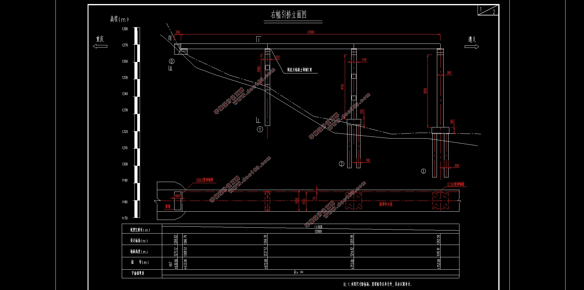
本方案采用3×40m预应力混凝土先简支后结构连续T梁桥,2桥梁全长120m。
3.2 上部结构尺寸拟定
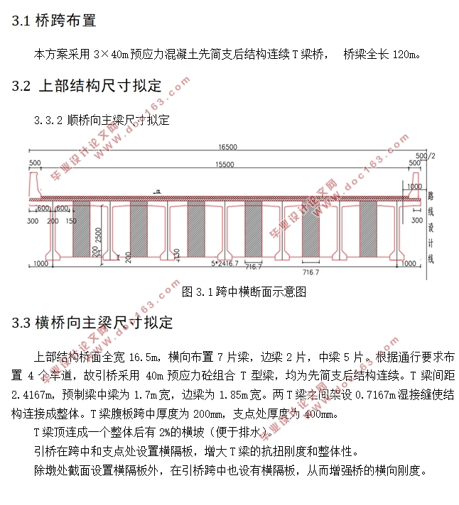
3.3.2 顺桥向主梁尺寸拟定
图3.1跨中横断面示意图
3.3横桥向主梁尺寸拟定
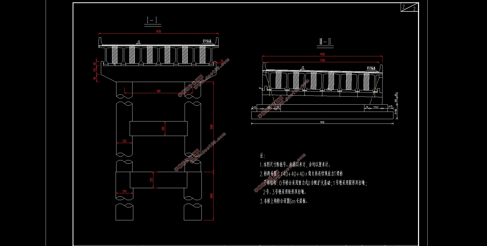
上部结构桥面全宽16.5m,横向布置7片梁,边梁2片,中梁5片。根据通行要求布置4个车道,故引桥采用40m预应力砼组合T型梁,均为先简支后结构连续。T梁间距2.4167m,预制梁中梁为1.7m宽,边梁为1.85m宽。两T梁之间架设0.7167m湿接缝使结构连接成整体。T梁腹板跨中厚度为200mm,支点处厚度为400mm。
T梁顶连成一个整体后有2%的横坡(便于排水)。
引桥在跨中和支点处设置横隔板,增大T梁的抗扭刚度和整体性。
除墩处截面设置横隔板外,在引桥跨中也设有横隔板,从而增强桥的横向刚度。
3.4下部结构尺寸拟定
3.4.1墩身尺寸拟定
下部构造依据墩柱高度采用双圆柱墩,圆柱墩构造简单、轻巧,适用于地基承载力较弱的地区。墩身受压受弯,要配有适量受力筋和构造钢筋。引桥桥墩拟采用双圆柱墩,半径为1.1m。 [资料来源:Doc163.com]
3.4.2桥台拟定
由于所在区域地基承载力承载力不高、台深高度较大,且跨径为40m,故选用肋板式桥台。但0 号桥台采用重力式 U 台配扩大基础。
3.4.3桩基础尺寸拟定
根据地质调绘和钻探资料,桥址区覆盖层为第四系(Q4el+dl)含砾粉质粘土、碎石、下伏基岩为奥陶系桐梓组-红花园(O1t+h)灰岩、白云岩、寒武系娄关山群灰岩、白云岩。钻孔灌注桩直径为2.2m,按纵向二排、横向二排,一共4根,采用C30混凝土,HRB335级钢筋, 。


 [资料来源:http://doc163.com]
目录
第1章绪论 1
1.1预应力混凝土连续梁桥的发展 1
1.2选题设计思想及意义 1
第2章桥梁方案比选 2
2.1桥梁设计原则 2
2.1.1安全性与适用性 2
2.1.2经济性和美观性 2
2.2设计方案 2
2.2.1预应力混凝土先简支后结构连续T型梁桥 3
2.2.2装配式预应力混凝土简支T型梁桥 3
2.2.3预应力混凝土变高度连续箱梁桥 3
第3章桥跨总体布置及结构尺寸拟定 5
3.1桥跨布置 5
3.2 上部结构尺寸拟定 5
3.3 横桥向主梁尺寸拟定 5
3.4 下部结构尺寸拟定 6
[资料来源:http://doc163.com]
3.4.1墩身尺寸拟定 6
3.4.2桥台拟定 6
3.4.3桩基础尺寸拟定 6
第4章 midas/civil建模 7
4.1 midas/civil建模概述 7
4.1.1计算几何特性 7
4.1.2.计算参数θ和α 8
4.1.3.计算各主梁横向影响线坐标 8
4.2 midas/civil建模 11
4.3主要参数说明 12
4.3.1 材料参数 12
4.3.2荷载参数 12
4.3.2边界说明 13
4.3.3施工阶段说明 13
第5章桥梁结构内力计算 14
5.1 恒载内力 14
5.2 活载内力 16
第6章预应力钢筋设计及预应力损失计算 19
6.1 预应力钢筋设计 19
6.1.1 纵向预应力筋估算 19
6.1.2 预应力筋的布置 23
6.2 预应力损失 23
6.2.1 预应力钢筋与管道壁之间的摩擦 24
6.2.2锚具变形、钢筋回缩和接缝压缩σl2 24
6.2.3预应力钢筋与台座之间的温差σl3 25
6.2.4混凝土的弹性压缩σl4 25
6.2.5预应力钢筋的应力松驰σl5 25
6.2.6混凝土的收缩徐变σl6 25
6.2.7 预应力损失计算结果 26
第7章次内力计算及内力组合 29
7.1 温度次内力 29
7.1.1 计算依据及方法 29
7.1.2 温度次内力计算结果 29
7.2 基础不均匀沉降次内力 34
7.3 预应力次内力 36
7.4 收缩次内力 38
7.5 徐变次内力 40
7.6 内力组合 42
7.6.1 承载能力极限状态组合 42
7.6.2 正常使用极限状态组合 44
第8章主要截面验算 47
8.1 承载能力极限状态截面验算 47
[来源:http://www.doc163.com]
8.1.1 正截面抗弯验算 47
8.1.2 斜截面抗剪验算 48
8.2正常使用极限状态截面验算 50
8.2.1使用阶段正截面抗裂验算 50
8.2.2 使用阶段斜截面抗裂验算 52
8.3 持久状况和短暂状况构件的应力验算 54
8.3.1 使用阶段正截面压应力验算 54
8.3.2 使用阶段斜截面主压应力验算 56
8.3.3 施工阶段正截面法向应力验算 59
8.3.4 受拉区钢筋的拉应力验算 61
第9章锚下局部承压验算 63
9.1局部受压区尺寸要求 63
9.2局部抗压承载力计算 64
第10章行车道板计算 66
10.1 中间单向板计算 66
10.1.1 恒载内力 66
10.1.2 活载内力 66
10.1.3 内力组合 68
10.2 外边梁悬臂板内力计算 68
10.2.1 恒载内力 68 [版权所有:http://DOC163.com]
10.2.2活载内力 69
10.2.3内力组合 69
10.3 配筋设计 69
10.3.1 支点处配筋 69
10.3.2抗剪验算 70
第11章盖梁计算 71
11.1.垂直荷载计算 72
11.1.1盖梁自重及内力计算 72
11.1.2活载横向分布系数 72
11.1.3活载横向分配后各梁支点反力 76
11.1.4恒载活载反力汇总 79
11.1.5双柱反力Gi计算 80
11.2盖梁各截面内力计算 81
11.2.1 恒载加活载作用下各截面的内力 81
11.3盖梁配筋设计 83
11.3.1截面纵向受拉钢筋计算 83
11.3.2复核截面尺寸 84
第12章桥墩墩柱设计 85
12.1荷载计算 85
12.1.1恒载计算 85
12.1.2活载计算 85
12.1.3双柱反力横向分布计算 85
12.1.4荷载组合 86
12.2截面配筋计算及应力验算 87
12.2.1作用于墩柱顶的外力 87
12.2.2作用于墩柱低的外力 88
12.2.3截面配筋计算 88
12.2.4 墩柱截面承载力验算 88
第13章钻孔灌注桩的计算 90
13.1荷载计算 90
13.2桩长计算 90
13.3桩的内力及位移计算 91
13.3.1桩的计算宽度b 91
13.3.2桩的变形系数 92
13.3.3桩身最大弯矩位置及弯矩计算 92
13.3.4最大冲刷线下深度Z处桩截面上的弯矩及水平压应力 92
13.4桩基配筋计算 95
13.4.1确定稳定系数φ,求As' 95
13.4.2选配钢筋 95
13.5桩的截面承载力验算 95
第14章桥台设计 97
14.1桥台计算资料 97
14.2 桥台荷载计算 99
结论 101
参考文献 102
致谢 103 [资料来源:http://www.doc163.com]
上一篇:基于UHPC的150m跨度连续梁桥结构设计(90m+150m+90m)(含CAD图)
下一篇:庙台子1号桥(4×40m预应力砼先简支后连续T梁桥)右幅设计(含CAD图)
