
某高新技术工业园区污水厂工程设计计算(含CAD图)
某高新技术工业园区污水厂工程设计计算(含CAD图)(任务书,开题报告,外文翻译,计算说明书12000字,CAD图11张)
摘要
本设计为某高新技术工业园区污水厂工艺设计,水厂分两期建设,处理规模为近期3000m3/d,远期9000m3/d。进水水质为:BOD=600mg/L,COD=300mg/L,TP=5mg/L,TN=55mg/L,SS=400mg/L。出水水质要求为:BOD≤50mg/L,COD≤10mg/L,TP≤0.5mg/L ,TN≤1.5mg/L SS≤10mg/L。
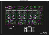
通过对不同污水处理工艺的比较与分析,结合本工程的具体情况,最终选择A2/O工艺作为本工程的处理工艺。其原理是将污水先后通过生化池厌氧区、缺氧区、好氧区,以达到同时去除有机物、脱氮、除磷的效果。该工艺具有流程简单,管理方便,运行费用低等优点,是一种广泛应用的污水生化处理工艺。
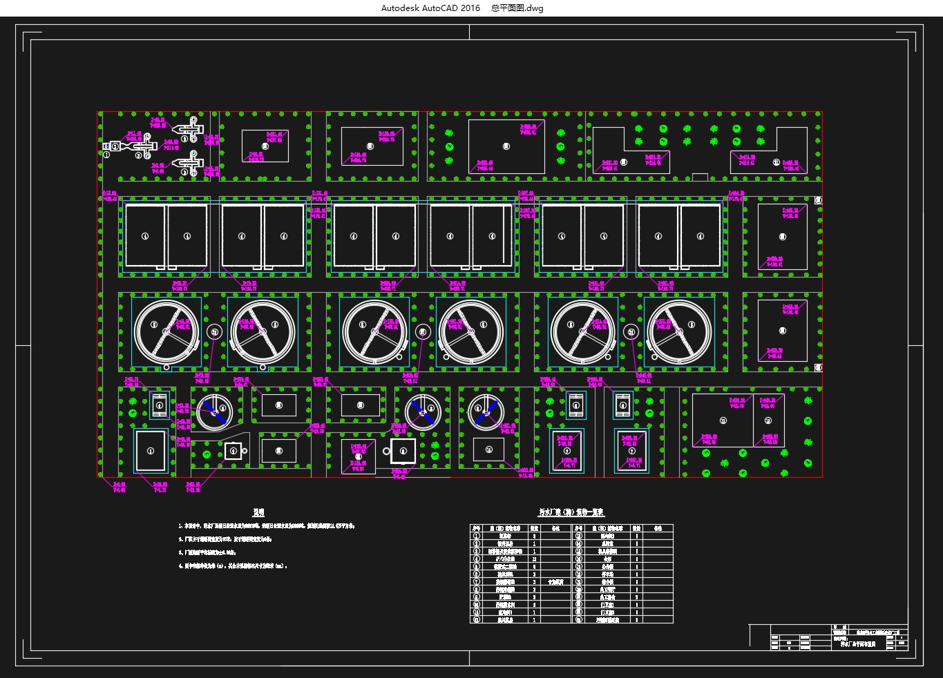
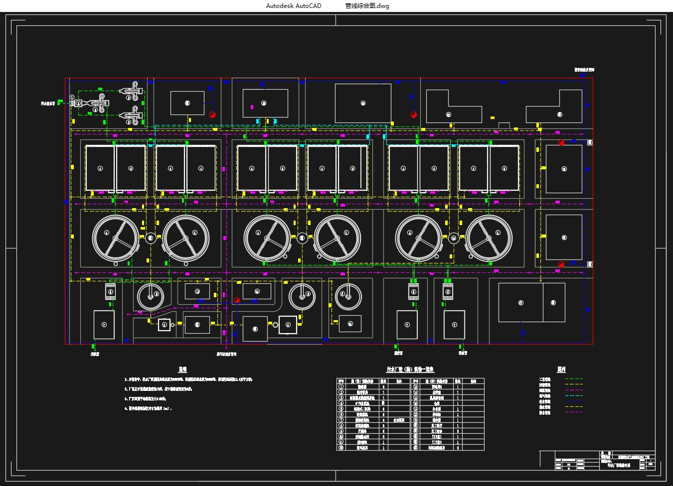
污水处理工艺流程为:进水→粗格栅→污水提升泵→细格栅→旋流沉砂池→A2/O生化池→辐流式二沉池→接触消毒池→出水。
污泥处理工艺流程为:污泥泵房→辐流式浓缩池→贮泥池→带式压滤机→泥饼外运。
关键词:高新技术工业园区污水厂;A2/O工艺;脱氮除磷;污泥处理
Design and calculation of a high tech industrial park wastewater treatment plant [资料来源:http://www.doc163.com]
Abstract
The project is a design of Tianlou Town sewege treatment plant in Guannan County,construction of two phases.The recent design scale is 3000m3/d and the long-term scale is 9000m3/d.The influent quality is shown as follow: BOD=600mg/L, COD=300mg/L, TP=5mg/L, TN=55mg/L , SS=400mg/L.Theeffluent water quality requires to reach the BOD≤50mg/L, COD≤10mg/L,TP≤0.5mg/L,TN≤1.5mg/L,SS≤10mg/L.
By comparing and analyzing different wastewater treatment processes,combining with the specific circumstances of this project,Anaerobic-Anoxic-Oxic process is chosen as the final process of this project.The principle is that the wastewater has passed the anaerobic zone, anoxic zone, aerobic zone, in order to remove the organic matter, the nitrogen, and phosphorus as the same time.The process has many advantages, such as simple process, easy management, low operating cost, etc..It is a widely used sewage biochemical treatment process.
Sewage treatment process is: inflow→coarse screen→ sewage lift pump →fine screens → rotational flow grit chamber → Anaerobic-Anoxic-Oxic Biochemical pool →radial-flow sedimentation tank →disinfection tank→effluent.
[资料来源:http://doc163.com]
Sludge treatment process is: sludge pumping room→ radial flow type concentrating pool → sludge storage tank→belt pressure filter press→transport of mud cake.
Key Words:WWTP; Anaerobic-Anoxic-Oxic process;nitrogen and phosphorus removal;sludge treatment
[资料来源:http://Doc163.com]
[资料来源:http://Doc163.com]
目录
摘要 1
Abstract 1
第一章概述 5
1.1 基本资料 5
1.2 污水水量及水质分析 5
1.3 方案比较及选择 6
第二章污水处理构筑物的设计计算 8
2.1 进水管 8
2.2 粗格栅和提升泵房 8
2.2.1 粗格栅的设计与计算 8
2.2.1 提升泵房的设计与计算 11
2.3 细格栅 12
2.4 沉砂池 14
2.4.1 沉砂池概述 14
2.4.2 沉砂池的比选 14
2.4.2 旋流式沉砂池的设计计算 15
2.5 A2/0反应池 17
2.5.1 设计参数 18
2.5.2 主要尺寸计算 19
2.5.3 剩余污泥量计算 20
2.5.4 曝气系统计算 20
2.5.5 管道系统计算 22
2.6 二沉池 24 [资料来源:https://www.doc163.com]
2.6.1 主要尺寸计算 25
2.6.2 进水部分设计计算 27
2.6.3 出水部分设计计算 28
2.6.4 刮泥设备选型 30
2.7 转盘滤池 30
2.7.1 转盘滤池概述 30
2.7.2 转盘滤池设计计算 31
2.8 消毒池及加氯间 32
2.8.1 消毒剂的选择 32
2.8.2 接触消毒池 33
2.8.3 加氯装置设计计算 35
第三章污泥处理构筑物的设计计算 36
3.1 污泥浓缩池 36
3.1.1 污泥浓缩池概述 36
3.1.2 设计参数 36
3.1.3设计计算 36
3.2 贮泥池 38
3.3污泥脱水机房 39
3.3.1设计说明 39
3.3.2设计计算 39
第四章构筑物高程计算 40
4.1 水头损失计算 40 [资料来源:http://www.doc163.com]
4.1 高程确定 40
第五章造价估算 42
第六章运行费用 44
6.1 装机容量和用电量 44
6.2 运行费用估算 44
6.2.1 动力费 44
6.2.2 药剂费 44
6.2.3 污泥运输费 44
6.2.4 人工费 44
6.2.5 总运行费用 45
参考文献 46 [资料来源:www.doc163.com]