9吨货车的驱动桥(后桥)的设计(含CAD零件装配图,STEP三维图)
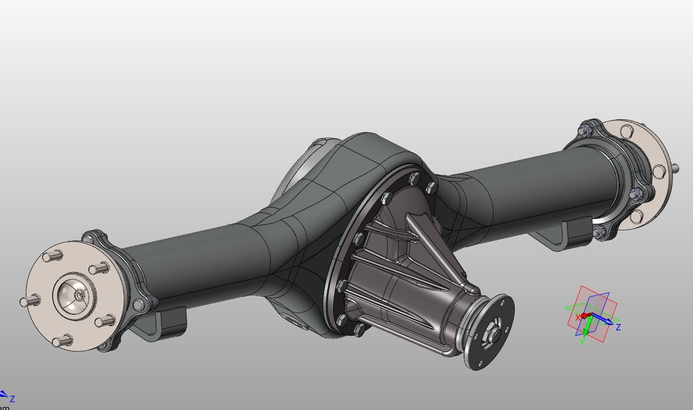
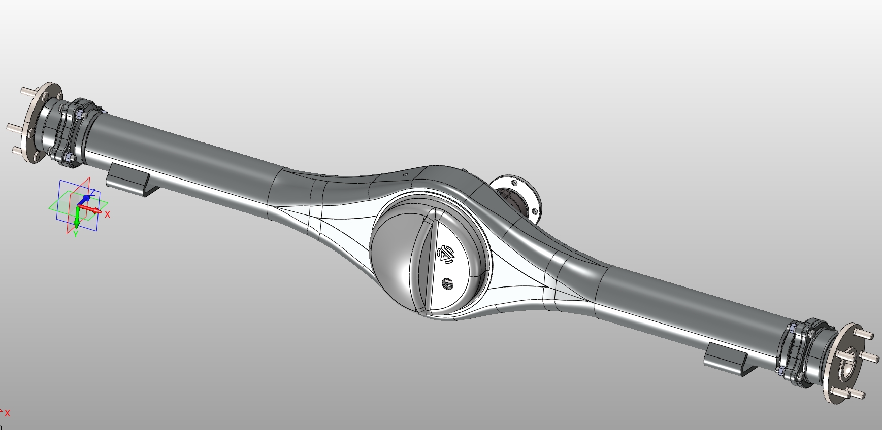
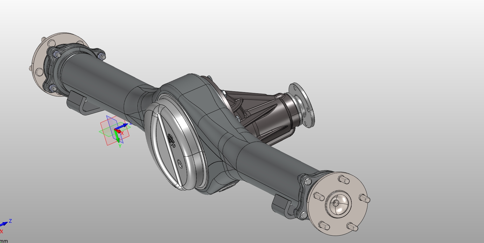
9吨货车的驱动桥(后桥)的设计(含CAD零件装配图,STEP三维图)(任务书,开题报告,文献摘要,外文翻译,论文说明书19000字,CAD图6张,STEP三维图)
摘要
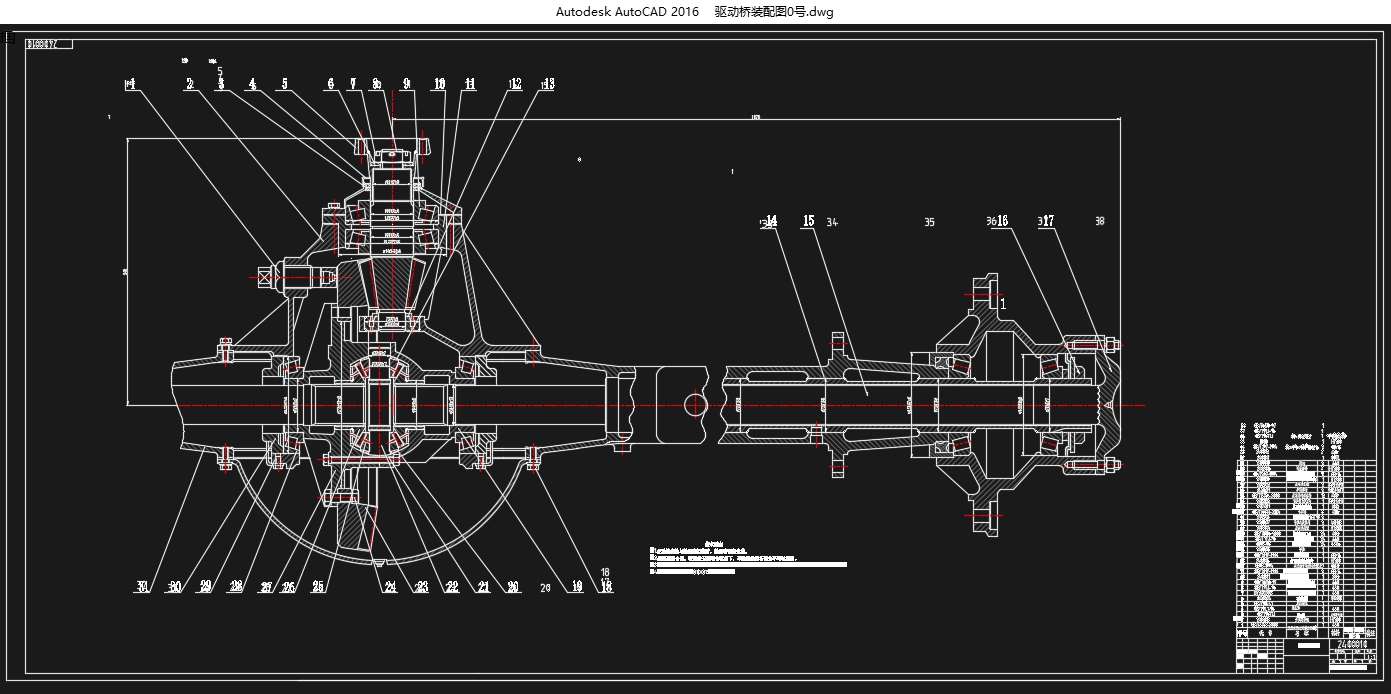
本次设计为总质量9吨货车驱动桥设计。汽车驱动桥作为汽车传动系中重要组成部分,它所处的位置是在传动系的末端,由主减速器、差速器、半轴和桥壳共同组成。它将经传动轴传来的发动机转矩通过主减速器、差速器、半轴等传到驱动车轮。
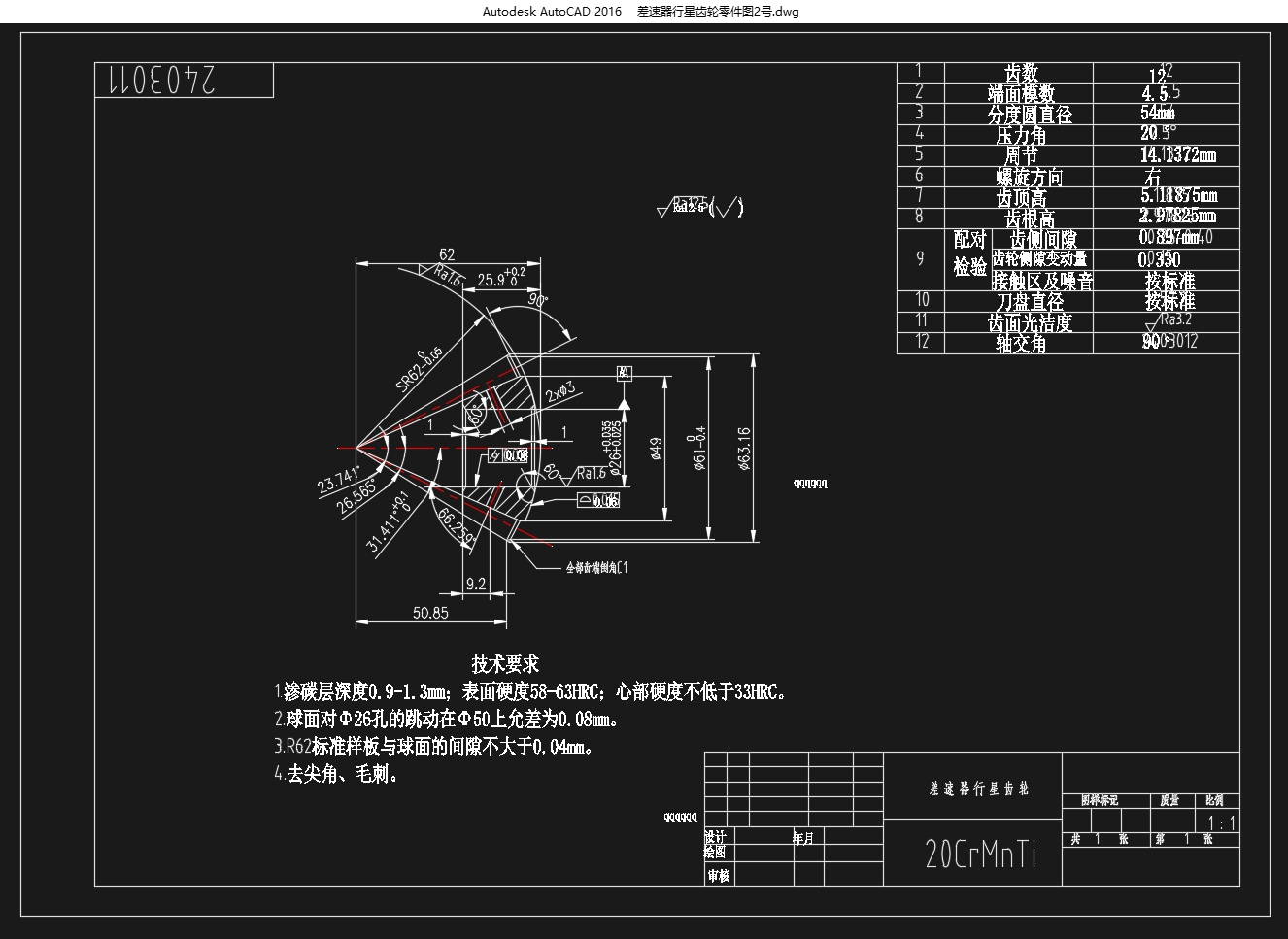
本说明书中,根据给定的参数,首先确定了驱动桥总成的结构形式,然后对主减速器进行设计。主要是对主减速器的结构形式进行选择,对相关的几何尺寸进行了设计。接着对差速器的形式进行了选定,并对差速器齿轮及差速器壳的几何尺寸进行了设计和计算。然后,对半轴的支承形式及尺寸,以及桥壳的形式和特点进行了选择和分析设计。并分别计算出各零件的工作载荷,根据标准要求对它们进行了校核。
本设计中采用了非断开式驱动桥,主要是考虑到这种类型的结构特点较为适合货车,因为这种结构类型具有一系列的优点,例如架构较简单,制造难度低,可靠性高,使用寿命长。采用单级主减速器,是因为其结构简单、体积及质量小且制造成本低。采用双曲面齿轮作为主减速器传动齿轮是由于其布置尺寸紧凑,承载负荷也较高,其传动平稳无噪声、强度也高。而差速器则采用了在货车中最为常见的普通锥齿轮差速器。由于载货汽车的载荷较大,因此本设计采用只承受传动系的转矩而不承受弯矩的全浮式半轴以及刚度和强度都较高的整体式桥壳。
关键词:驱动桥;主减速器;差速器;半轴;桥壳
Abstract
This design is for the medium truck axles. Automotive drive axle as an important part of car in the drive train, it set up at the end of the transmission system, by the main reducer, differential machine, half shaft and finally axle housing, Manufacturing level is the top priorityIt will be the drive shaft from the torque engine torque form of the differential reducer, auto seek breakthrough has important significance to our country. differential tags the main reducer to drive the wheels.
In this manual, according to the given parameters, the set of drive axle first of all to carry on the design of main reducer. Is mainly about the structure of main reducer, and geometry size design. Secondly, to choose tag the main reducer, Commercial vehicle market as an differential and the gear has carried on the design and hypoid gear as the main drive gear speed reducer calculation. After, the size of half shaft, support form, as well as the bridge shell and characteristics are analyzed in the form of design. Then, on the strength of the gear check.
Using the broken open drive extreme emphasis on durability, reliability and fuel economy of a marketable is because it has simple structure, good processing manufacturability, manufacturing easy, tear open outfit, easy to adjust, reliable work, excusing single stage the main reducer, because of its simple structure, small volume and quality and manufacturing cost is low. The hypoid gear as the main drive gear speed reducer is due to Elevate the status of domestic commercial vehicle on a global scaliest size compact, bearing load is high; its drive smoothly without noise, the intensity is high. Using common bevel gear differential, due to its simple structure, stable, easy to manufacture. Due to the truck load is bigger, so this design USES only under the transmission torque without full floating half shaft under bending moment and the integral bridge shell stiffness and strength is higher.
Key Words: Drive axle; the main reducer; Differential; Half shaft; Bridge shell
[版权所有:http://DOC163.com]
[版权所有:http://DOC163.com]

目录
第1章绪论 1
1.1目的及意义 1
1.2驱动桥简介 2
1.3货车驱动桥的设计要求 2
1.4驱动桥总成的结构形式及布置 3
第2章驱动桥主减速器设计 4
2.1主减速器形式及选择 4
2.2主减速器的齿轮类型 4
2.3主减速器主、从动锥齿轮的支撑方式及调整 6
2.3.1主动锥齿轮的支撑 6
2.3.2从动锥齿轮的支撑 6 [来源:http://Doc163.com]
2.3.3锥齿轮轴承的预紧与调整 7
2.4主减速器基本参数的设计计算 8
2.4.1主减速比 的确定 8
2.4.2主减速器齿轮计算载荷的确定 8
2.4.3主、从动齿轮齿数的选择 10
2.4.4从动锥齿轮节圆直径及端面模数的选择 10
2.4.5双曲面齿轮齿宽 的选择 11
2.4.6双曲面小齿轮偏移距及偏移方向的选择 11
2.4.7螺旋角β的选择 12
2.4.8法向压力角 及铣刀盘名义直径的选择 13
2.4.9主减速器圆弧齿双曲面齿轮的几何尺寸计算 13
2.5主减速器圆弧齿双曲面齿轮的强度计算 15
2.5.1单位齿长上的圆周力 15
2.5.2双曲面齿轮轮齿的计算弯曲强度计算 16
2.5.3轮齿的齿面接触强度计算 17
2.6主减速器齿轮的材料选择及热处理 17
第3章载货汽车差速器的设计 19
3.1对称式锥齿轮差速器差速原理 19 [来源:http://Doc163.com]
3.2对称式锥齿轮差速器中的转矩分配 20
3.3差速器齿轮设计 21
3.3.1行星齿轮数目及行星齿轮球面半径 的设计 21
3.3.2行星齿轮与半轴齿轮齿数的选择 21
3.3.3差速器锥齿轮模数及半轴齿轮分度圆直径的初步确定 22
3.3.4差速器几何尺寸计算 22
3.4行星齿轮轴的选用 23
3.5差速器强度计算 24
第4章驱动车轮的传动装置的设计 26
4.1半轴形式 26
4.2全浮式半轴计算载荷的确定 26
4.3全浮式半轴杆部直径的初选 27
4.4半轴的强度计算 27
4.5花键的剪切应力与挤压应力 28
4.6半轴材料及热处理 28
第5章驱动桥壳的设计 30
5.1驱动桥壳的功用和设计要求 30
5.2驱动桥壳结构方案分析 30
5.3桥壳的静弯曲应力计算 31
5.4在不平路面冲击载荷作用下的桥壳强度计算 32
5.5汽车以最大牵引力行驶时的桥壳强度计算 33
5.6汽车紧急制动时的桥壳强度计算 34
第6章总结 36
6.1 结论 36
6.2展望 36
参考文献 38
致谢 39 [资料来源:Doc163.com]
上一篇:EQ1092F19D1型长头柴油载货汽车后悬设计(含CAD零件装配图)
下一篇:东风日产逍客五挡变速器设计(含CAD零件装配图,CATIA三维轴图)
