S195柴油机机体三面精镗组合机床总体设计及夹具设计
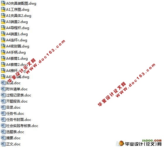
S195柴油机机体三面精镗组合机床总体设计及夹具设计(选题审批表,任务书,开题报告,过程检查表,毕业论文13000字,cad图纸13张)
摘 要
夹具设计是机械制造厂里的一种工艺装备,有机床夹具,焊接夹具,装配夹具,检验夹具等,一般的机床夹具是作为机床的辅助机构设计的,而组合机床夹具是作为机床的主要组成部分,其设计工作是整个组合机床设计的重要部分之一。组合机床夹具应便于实现定位和夹压的自动化,并有动作完成的检查信号。夹具体在机床上的安装都是通过夹具体上的安装基面与机床上的相应表面的接触或配合实现的。当夹具体在机床工作台上安装时,夹具的重心应尽量低,重心越高则支承面应力越大,夹具底面四边应凸出,使其接触良好,或底部设置四个支脚。当夹具体在机床主轴上安装时,夹具安装基面与主轴相应表面应有足够的配合精度,并保证安装稳定可靠。
关键词: 夹具设计 组合机床 总体设计
Abstract
Tongs design is a kind of craft that machine manufactory in equip, organism bed tongs, welding tongs, assemble tongs, examination tongs etc., the general machine bed tongs is an assistance to be used as the machine bed organization design of, but the combination machine bed tongs is an importance to be used as the machine bed to constitute the part primarily, its design work is whole combination machine bed design part of a. Combination the machine bed tongs shoulds be easy to realize fixed position with clip the automation that press, also the check signal that action complete. The tongs all passes in the machine the gearing on the bed what tongs the gearing on realizes with superficial contact in the cowgirl on the bed in machine or matches.When the tongs installs in the machine bed work on the stage, the center of gravity of the tongs should be as far as possible low, center of gravity the more high an accepts should the dint is more big, the tongs bottom four directions should bulge, make its contact good, or the bottom establishes four a feets.When the tongs installs on the machine bed principal axis, the tongs install the to should have the enough match accuracy with principal axis cowgirl surface, and guarantee the gearing the stability dependable.
[资料来源:http://www.doc163.com]
Keywords: tongs combination the machine bed clip the automation
任务、目的与要求:任务:S195柴油机体三面精镗组合机床总体设计及夹具设计
精加工缸套孔Ф118H10,Ф111H8,Ф110H7,曲轴孔Ф195H7,Ф78H7;平 衡轴孔Ф52M7, 凸轮轴孔Ф35H7;调速轴孔Ф47H7,25V7,起动轴孔37H7
⑴、机床要求运转平稳,结构简单,工作可靠,装卸方便,维修及调整便利。
⑵、加工精度应符合零件图要求。
⑶、夹具设计要求定位合理,夹紧可靠,结构简单,操作方便,调试及维修方便,提高生产效率。
1. 明确设计任务与收集设计资料;
2. 拟订方案,绘单图;
3. 分析计算;
4. 审方案,改造设计;
5. 绘制夹具总装配图;
1. 6. 绘制夹具图中主要零件的总装配图。
[版权所有:http://DOC163.com]
目 录
引言……………………………………………………………………………………2 [资料来源:http://doc163.com]
1 工艺方案的拟定……………………………………………………………………3
2 定位基准及夹位点选择……………………………………………………………4
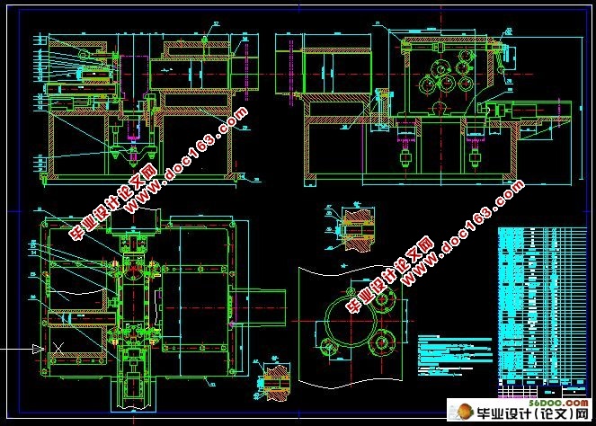
3 组合机床总体设计——三图一卡…………………………………………………6
3.1被加工零件工序图………………………………………………………………6
3.2加工示意图………………………………………………………………………7 [资料来源:http://doc163.com]
3.3动力部件的选择……………………………………………………………………9
3.4组合机床生产率的计算……………………………………………………………11
3.5机床联系尺寸图……………………………………………………………………14
4 夹具设计……………………………………………………………………17
4.1设计步骤……………………………………………………………………………17 [资料来源:http://www.doc163.com]
4.2 定位支承系统……………………………………………………………………17
4.3 定位误差的分析计算……………………………………………………………17
5 导向装置……………………………………………………………………………21
6 夹紧力的确定……………………………………………………………………22
7 夹紧机构……………………………………………………………………………24
7.1设计夹紧机构应满足的要求……………………………………………24
7.2夹紧气缸…………………………………………………………………………25
7.3活塞杆的计算………………………………………………………………………25
8.夹具体设计…………………………………………………………………………27
8.1对夹具体的要求…………………………………………………………………27
[资料来源:http://Doc163.com]
8.2夹具体的技术要求…………………………………………………………………28
结束语………………………………………………………………………………29
参考文献………………………………………………………………………………30
附件清单………………………………………………………………………………31
[来源:http://www.doc163.com]
上一篇:柴油机气缸体顶底面粗铣夹具设计
下一篇:柴油机机体的加工工艺及夹具设计
