
钻缝纫机底板侧面孔加工的夹具设计(含CAD零件装配图)
钻缝纫机底板侧面孔加工的夹具设计(含CAD零件装配图)(含CAD图)(论文说明书10000字,CAD图纸8张)
摘 要
设计的零件为钻缝纫机底板零件,设计的主要任务是设计其加工制造工艺及加工过程中的夹具设计。设计中首先要对零件的加工工艺进行仔细的分析。这次设计中对零件的加工工艺性分析从零件的设计图着手,分析零件的毛坯,基准,流程和工艺参数等技术性问题,
在完成分析后,后各个分析的结果进行汇总,编制零件的加工工序卡,流程卡等工艺文件。此次设计的设计任务还包括夹具设计。在此设计过程中需要设计对 8mm槽的进行铣槽加工的夹具,分析零部件的加工钻缝纫机底板基准和夹紧方式,完整的零件设计和装配图,将其视为非组件图中的固定装置和零件图。规划和设计工作包括三个步骤:
在第一阶段,要对零件设计图纸进行仔细的阅读,查阅相关技术资料,了解其国内外加工行情况,查阅同类型零件的加工现状。并对重要的数据进行记录一遍后期查阅。
第二步是确定初步整合的数据,对组成部分进行复合分析,确定处理和分离的顺序、工艺部分的安装过程(如相位或位置)。选择机器中使用的每一个步骤的仪器,工具的类型和测量仪器。通过员工共同发展的过程,实现了理论与实践的统一。常常需要提出几个方案,进行分析比较后再确定。查阅《切削用量手册》等资料并进行计算确定。为了保证生产的节拍,必须规定切削用量,并不能随意改变。确定加工余量、工序尺寸及公差是要控制各工序的加工质量以保证最终加工质量。编制零件的加工工序卡片。分析工序中零件的加工工序定位基准,分析定位方案,夹紧方案等,绘制零件的夹具装配总图零件图。 [资料来源:Doc163.com]
在最后的设计阶段主要是对前期的设计工作量进行汇总,编制设计论文正文,综合各方面的信息在论文中对零件的加工工艺及夹具的设计进行详细的分析与论述,最终完成设计说明书的编制。
关键词:加工工艺 夹具设计 工艺流程 专用夹具
Abstract
The main task of the design is to design the manufacturing process and the fixture design. In the design, first of all, the processing technology of parts should be carefully analyzed. In this design, the processing technology analysis of the parts starts from the design drawing of the parts, and analyzes the technical problems such as blank, benchmark, process and process parameters of the parts,
After the completion of the analysis, the results of each analysis are summarized, and the processing procedure card, process card and other process documents of the parts are prepared. After analyzing the processing technology of the parts, it is necessary to design the processing fixture according to the actual requirements of the process flow. In this design process, it is necessary to design the fixture for milling the 8mm groove, analyze the machining fork datum and clamping mode of the parts, and finally complete the design of the machining fixture of the parts, and draw the assembly drawing of the machining fixture and the drawing of non-standard parts. This design task is planned to be designed in three stages, as follows:
In the first stage, we should carefully read the design drawings of the parts, consult the relevant technical data, understand the domestic and foreign processing conditions, and consult the processing status of the same type of parts. And record the important data for later reference.
In the second stage, it is necessary to comprehensively analyze the part drawing based on the preliminary data, determine the processing sequence and method of the part, and divide the process, installation or work position and work step, etc. And select the machine tool model, cutter, fixture and measuring tool used in each process. Draw up the technological route from the reality, combine theory with practice and workers. It is often necessary to put forward several plans for analysis and comparison before they are determined. Consult "cutting parameters manual" and other data and make calculation and determination. In order to ensure the production beat, it is necessary to specify the cutting parameters, which cannot be changed at will. The determination of machining allowance, process dimension and tolerance is to control the processing quality of each process to ensure the final processing quality. Prepare the process card of parts. Analyze the positioning datum, positioning scheme, clamping scheme, etc. of the machining process of the parts in the process, and draw the part drawing of the fixture assembly general drawing of the parts.
In the last stage of design, it is mainly to summarize the previous design work, prepare the main body of the design paper, and analyze and discuss the processing technology of parts and the design of fixture in detail in the paper based on the comprehensive information of all aspects, and finally complete the preparation of the design specification.
Key words: process fixture design process specific fixture
零件的工艺性分析
此次设计的零件的表面结构简单,加工精度比较高,零件的部分加工面为有高精密零件配合面,部分加工表面为次要表面即非配合表面,所以表面的粗糙度和加工精度是不相同的,在设计图纸部分配合面的加工精度一般要求较高,不是配合面的地方加工精度相对来说较低。结构是简化零件加工的优选工艺的一部分。获得的部分设计的钻孔、铣削和表面加工方法得到的缝纫加工设计。机床的加工精度是一个更好的配件。加工零件时,加工面是开的,现场加工无死角。
[版权所有:http://DOC163.com]


[资料来源:https://www.doc163.com]
目 录
摘 要 I
Abstract II
第一章 绪论 1
1.1. 设计的意义 1
1.2. 设计的目的 1
1.3. 毕业设计的内容 1
第二章 零件结构的工艺性分析 3
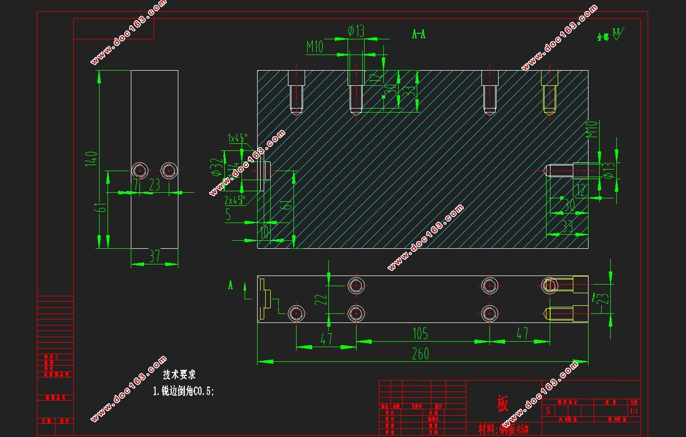
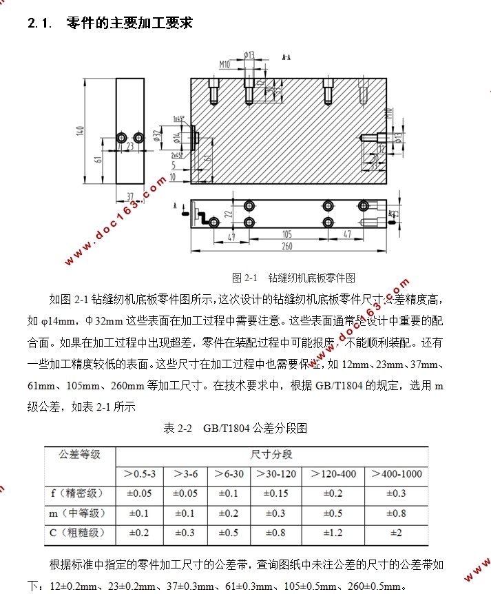
2.1. 零件的主要加工要求 3
2.2. 零件的工艺性分析 4
第三章 零件毛坯的选择 5
3.1. 加工毛坯的选择 5
3.2. 加工基准的选择与判定 5
3.3. 零件加工方法的选择 6
3.4. 零件的工序划分 6
3.5. 确定装夹方法 8
3.6. 加工设备的确定 9
3.7. 刀具的选择 9
3.8. 加工切削用量及加工工时计算 10
3.8.1. φ50mm盘铣刀铣260×140面切削用量计算 10
3.8.2. 钻攻6-M10加工切削参数计算 11
3.8.3. 铣14mm圆孔加工切削参数计算 12 [来源:http://www.doc163.com]
第四章 专用钻孔夹具设计 14
4.1. 问题的提出 14
4.2. 定位方案设计及定位原件选择 14
4.2.1. 定位方案设计 14
4.2.2. 定位元件的选择 15
4.3. 夹紧力及切削力的计算 15
4.3.1. 夹紧力分析 15
3.3.2切削力计算 15
4.4. 夹具体的设计 16
4.5. 刀具引导装置的设计 17
4.6. 定位精度分析 17
4.7. 夹具的简单操作说明 17
结束语 19
致 谢 20
参 考 文 献 21
上一篇:变速箱箱体端面铣削加工工艺装备设计(含CAD夹具图)
下一篇:左支座零件的加工工艺及夹具设计(含CAD零件图夹具图)