液压自动定心夹具结构设计(新品)
摘要
机器的振动是一种常见的现象,但是除了一些利用振动工作的机器外,对于一般的机器来说,振动是有害的。振动将使机器的零部件承受附加的动载荷,明显的加速轴承、轴颈的磨损影响机器的工作性能,降低机器的精度,缩短机器的工作寿命。而使旋转机械产生振动的主要原因之一是由于转子不平衡质量的惯性力或惯性力矩所造成的。所谓的平衡即是根据转子——支承系统的动力学特性,并通过测量转子——支承系统有关侧点振动与转速同频分量的幅值大小和相位信息来判断不平衡大小和位置,以便采取措施进行平衡的一门技术;而平衡机的功能就是测量转子的不平衡量。
在立式平衡机上对工件进行平衡测量时需要附带夹具,定心夹紧机构能够在准确自动定心或对中的同时夹紧工件。因此,机构中与工件定位基准相接触的元件,既是定位元件又是夹紧元件。当元件被加工面以中心要素(轴线、中心平面等)为工序基准时,采用定心夹紧机构,能实现基准重合,可提高定位精度。本设计采用弹性夹头这种定心夹紧机构,由液压系统提供动力,制动器实现主轴的制动。
关键词:平衡机、液压、弹性夹头、制动器
ABSTRACT
The vibration machine is a common phenomenon, but apart from some work of vibration of the machinery, for the general machinery, the vibration is harmful. Under the influence of the vibration, machine parts will bear the additional dynamic load, significantly speeding up the bearings and the journal of wear and tear, which affect machines’ work performance, and reduce the accuracy of machines, shorten the machines’ working life. One of the main reason for the rotating machinery to produce vibration is due to the rotor imbalance quality of inertia or moment of inertia. The so-called balance that is in accordance with the Rotor – Support System’s dynamic character, and by measuring the Rotor - Support system at the side of the vibration and speed-frequency components of the same size amplitude and phase information to determine the size and location of imbalance, a technology in order to take measures to balance . While balancing machines feature is the measurement of the imbalance of the rotor.
[资料来源:www.doc163.com]
Measurement of the workpiece to balance need fringe fixture in the vertical balancing machines, centering clamping institutions can accurately or automatic centering on the workpiece while clamping the workpiece. Therefore, agencies that contact with the positioning benchmark of the workpiece, is not only positioning devices but also clamping components. When the processing plane of workpiece use a central element (axis, the center plane, etc.) as the benchmark process, using centering clamping institutions, which can achieve the benchmark coincidence and improve positioning accuracy. The centering clamping institution that used in this design is a flexible chuck, which provided the impetus by the hydraulic system, and whose spindle braked by the brakes.
Key words: the balancing machines, hydraulic, flexible chuck, brakes
立式硬支承平衡机的工作原理
硬支承平衡机的振动系统(支承加上工件)的固有频率远高于其工作转速,其支承系统的振动振幅与不平衡量所产生的离心力成正比,因此,平衡机的工作频率只要远低于支承系统的固有频率,就可由支承的振幅(或轴承所受的力)直接反映出不平衡离心力。即转子的不平衡量是以力的形式作用在支承上,只要测出支承反力就能求得不平衡量,故硬支承平衡机有时亦称为测力型平衡机。 [来源:http://Doc163.com]
单面平衡机的结构基本上有两种类型,一种如图a)所示,转子1可安装在由弹性元件3所支承的旋转主轴2上,主轴2可由电机经皮带轮驱动(如图所示)或采用联轴节驱动。一般情况下,主轴事先已精确平衡。当平衡机的工作转速远高于转子 — 支承系统的固有频率时,系统在不平衡离心力的作用下为单自由度平动系统,系统的振幅正比于转子的静不平衡量,因此,可根据系统的振幅确定转子的静不平衡。
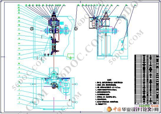
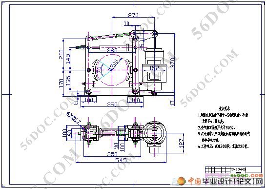
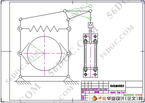
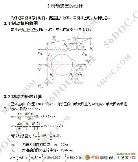
本论文主要设计一种由液压驱动的自动定心夹具,运用液动力推动活塞杆来实现夹具的夹紧和松开。主要完成以下任务:液压定心夹具的系统设计,各液压元件的计算与选择,液压泵的选择计算,液压回路的设计,工作头(弹性夹头)的设计计算,主轴制动器和固定簧板的设计计算,以及各主要元件的选择验算,绘制系统油路图、零件图和系统装配图。
[资料来源:http://doc163.com]
[来源:http://Doc163.com]
目录 17000字
中文摘要 Ⅰ
ABSTRACT Ⅱ
1 绪论 1
2 单面立式硬平衡机 2
2.1立式硬平衡机的工作原理 2
2.2方案确定 3
3 制动装置的设计 4
3.1 制动机构简图 4
3.2 制动力矩的计算 4
3.3 YDWZ 200/25型制动器的使用条件 6
3.4 复位弹簧的计算 6
3.5 摆架系统的设计与计算 7
3.5.1频率比的选取 7
3.5.2固有频率的计算 7
4 簧板 9
5 液压定心夹具 10
5.1 液压定心夹紧机构的工作原理 10
5.2 弹性夹头的设计计算 11
5.3 碟形弹簧 12
5.4 液压系统设计 13
5.4.1液压传动系统的流程设计 13
5.4.2明确传动系统设计的要求 13 [资料来源:http://www.doc163.com]
5.5 工况分析 15
5.5.1液压系统图的拟订 15
5.5.2液压回路的选择 15
5.6 液压系统的组成与特点 17
5.6.1液压系统的组成 17
5.6.2液压系统的特点 17
5.7 液压元件的选择计算 18
5.7.1液压泵的初步选择 18
5.7.2液压缸的设计和计算 20
5.7.3缸筒和缸盖的结构计算 20
5.7.4液压泵站 22
5.7.5液压介质的选择 23
5.7.6泵组的选择 24
5.7.7油箱组件的设计计算 24
5.7.8油管及辅助元件的选择计算 28
5.7.9液压管路的设计计算 29
5.7.10空气过滤器及液位器的选择 31
5.7.11过滤器组件的选择 31
5.7.12压力表及压力开关的选择 31
5.8 液压定心夹具的设计需注意的问题 32 [版权所有:http://DOC163.com]
6 总结 33
参考文献 34
下一篇:汽车连杆加工工艺及夹具设计
