
多点防盗报警系统的设计
多点防盗报警系统的设计(任务书,开题报告,外文翻译,论文15000字)
摘 要
本文分析了多点防盗报警系统的基本构造并且简单介绍了其工作原理,设计了与之配套的多点报警器。该报警器利用STC89C52单片机作为核心器件控制整个系统运作;热释红外探头探测是否有人闯入探测范围,并将检测到的数据送至单片机进行处理后显示;用DS1302来控制系统的时间准确;由按键来控制撤防和布防,用以启动系统和终止系统的报警。并且按键还模拟有人闯入系统进行报警;由LCD液晶屏1602控制来显示时间以及设定好的报警时显示的信息;由LED灯和蜂鸣器组成的报警电路实现了声光报警,当有人闯入报警系统的侦查范围,报警电路就会启动。
本篇论文从硬件电路的原理分析、软件编程的实现过程、电路仿真和调试等内容进行分析,实现了控制器的检测、显示和控制功能。
关键词:单片机 液晶管 红外线热释模块
Design of Multi-point burglar alarm system
Abstract
The main body of this paper analyses the basic structure of multi-point anti-theft alarm system , simply introduces its operation principle and states the whole design of the multi-point anti-theft alarm. The alarm system herein operates under the total control of the MCU marked STC89C52. While the pyroelectric infrared sensor keeps on detecting burst-in of human in the detection range, the detection data is transferred to the MCU to be processed and displayed. The chip marked DS1302 operates to control the system in accordance of accurate time.The button keyboard operates to control the alarm to be on or off, in order to decide start and stop of the alarm system. Additionally the buttons imitates a burst-in of human. The screen LCD1602 displays the settled time and the alarm information. The combination of LED lights and a buzzer realize alarms with both sound and light, which begins alarming right after the burst-in of human.
The design embodied herein shows the serial functions of detecting, displaying and controlling, through the analysis of hardware circuits,the compiling of software programs, the simulation and debugging of the circuit system and etc.
Key Word:SCM; LCD tube; Pyroelectric infrared module
[资料来源:http://www.doc163.com]


目 录
摘 要 I
Abstract II
第一章 绪 论 1
1.1课题背景 1
1.2报警器发展现状 1
1.3课题任务与要求 1
1.4课题安排 2
第二章 硬件电路设计 4
2.1方案设计 4 [资料来源:Doc163.com]
2.2系统处理模块 5
2.2.1系统模块的方案选择 5
2.2.2 STC89C52芯片介绍 5
2.2.3复位电路 7
2.2.4晶振电路 7
2.3采集模块 8
2.3.1采集模块的方案选择 8
2.3.2被动式红外传感器 8
2.3.3主动式红外传感器 9
2.3.4采集模块的选择 9
2.3.5采集模块在电路中的实现 9
2.4计时模块 10
2.4.1计时模块的方案选择 10
2.4.2 DS1302简介 11
2.4.3 DS1302功能实现 12
2.5 显示模块 13
2.5.1显示模块的方案选择 13
2.5.2 LCD1602的介绍 14
2.6 按键电路 15
2.7 报警电路 16
第三章 软件设计 18
3.1 总程序流程图 18 [来源:http://www.doc163.com]
3.2 LCD显示程序设计 19
3.3 报警程序设计 20
3.4 DS1302的程序设计 21
第四章 系统调试 23
4.1 软件的编写 23
4.2 硬件的仿真结果 23
4.3 硬件调试 24
4.4 调试过程中遇到的问题 27
结束语 28
参考文献 29
致 谢 30
附 录1 实验程序 31
(1) 实验主程序 31
(2) Ds1302子程序 35
(3)1602子程序 39
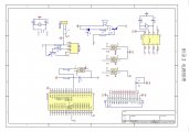
附录2 电路原理图 43
[资料来源:http://www.doc163.com]