高频开关稳压电源设计

高频开关稳压电源设计(任务书,开题报告,外文翻译,论文12000字)
摘要
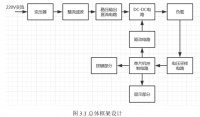
阐述了用AT89C51单片机输出PWM信号控制BUCK主电路中晶体管开关通断,利用AD模数转换反馈输出电压的采样值于是以此调节PWM占空比实现稳压输出的功能。另外附带3个功能按键和液晶显示。采用15V直流作为BUCK电路的输入电压,输出为3~12V电压值而且步进可调。本设计还通过C语言实现PID算法,程序数字滤波等等一系列计算。总体电路仿真软件为Proteus,C语言编程软件为Keil。
本文最终是希望设计出一款智能简单的可控开关电源,能够实现DC/DC变换器的功能而且输出电压值可调。输出电流不超过2A。因为开关电源的电能转换效率很高在人们的日常生活当中也有普遍使用,所以想利用单片机,按键以及液晶显示等低成本器件使得开关电源让用户体验更加良好。
关键词:开关电源;PWM;51单片机
Abstract
This paper expounds the use of AT89C51 single chip microcomputer output PWM signal to control the switching of the transistor in the BUCK main circuit, and the use of AD analog-to-digital conversion feedback output voltage sampling value so as to adjust PWM duty ratio to achieve voltage stabilization output function. It also has 3 function keys and LCD display. Using 15V dc as the input voltage of BUCK circuit, the output voltage is 3 ~ 12V and can be adjusted step by step. This design also through C language PID algorithm, program digital filtering and so on a series of calculations. The overall circuit simulation software is Proteus, and the C language programming software is Keil. [资料来源:http://www.doc163.com]
Finally, this paper hopes to design an intelligent and simple controllable switching power supply, which can realize the functions of DC/DC converter and the output voltage value can be adjusted. The output current does not exceed 2A. Switching power supply is widely used in People's Daily life because of its high power conversion efficiency. Therefore, we want to make use of low-cost devices such as single-chip microcomputer, keys and liquid crystal display to make switching power supply provide better user experience.
Key words: switching power; PWM 51; SCM
[资料来源:https://www.doc163.com]


目录
第1章绪论 1
1.1课题目的和意义 1
1.2课题相关背景 1
1.3 课题基本要求 2
第2章高频开关电源原理及方案选择 3
2.1高频开关电源变换器 3
2.1.1线性变换器 3
2.1.2 Buck变换器 4
2.1.3 Boost变换器 5
2.1.4 Buck-Boost变换器 5
2.2开关电源的驱动方式 6
2.3案的选择 6
第3章硬件电路设计 8 [资料来源:https://www.doc163.com]
3.1总体框架 8
3.2 BUCK电路参数计算和分析 8
3.3 AT89C52单片机系统 10
3.4电路供电辅助单元 12
3.5电压检测电路 12
3.6 A/D采样电路设计 13
3.7按键电路 14
3.8液晶显示电路 15
3.9小结 15
第4章软件设计 16
4.1主程序设计 16
4.2按键扫描子程序 16
4.3 LCD1602显示子程序 17
4.4 ADC0832转换子程序 18
4.5 PWM产生子程序 19
4.6 PID子程序 19
第5章系统仿真与调试 21
5.1硬件模块调试 22
5.1.1电路供电辅助单元调试 22
5.1.2 PWM波形调试 22
5.1.3功率开关管的调试 22
5.2电源性能仿真结果 22
5.2.1仿真结果 22
5.2.2最大输出电流的测试 23
5.2.3电压调整率的测试 23
5.2.4纹波电压的测试 24
第6章小结 25
参考文献 26
致谢 27
附录 28
[资料来源:http://Doc163.com]
