基于51单片机的步进电机控制系统设计
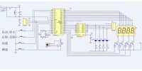
基于51单片机的步进电机控制系统设计(论文17000字,源代码,元件清单)
摘要:步进电机是一种由电脉冲信号控制的,用于将电脉冲转变成角位移的电机。它体积小,成本低,易控制,因此广泛应用于各种领域中。近些年,微型计算机的发展使得利用单片机来控制步进电机的工作成为可能,从而代替了原来那些复杂的控制设备。
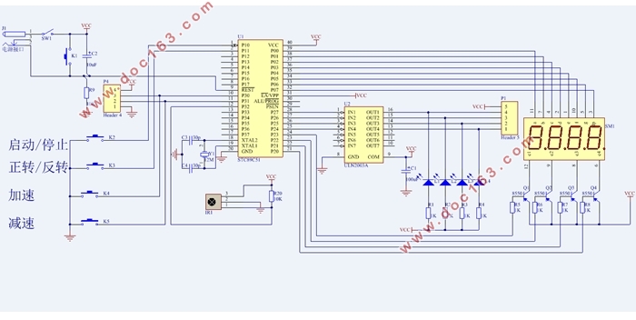
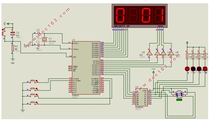
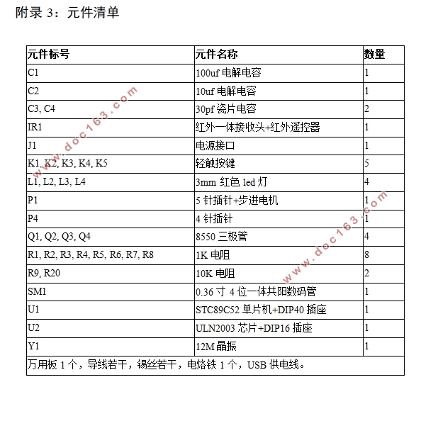
本论文以51单片机作为核心控制芯片,设计了一款步进电机控制系统。它以28BYJ-48步进电机作为被控对象,以STC89C52单片机作为核心控制模块;通过五个按键控制步进电机完成不同的功能,包括电路的复位,步进电机的启动/停止,正反向旋转,加速和减速等5个功能;以4位共阳数码管作为显示器,实时显示步进电机的工作状态;为了方便远程操作该控制系统,本论文还增加了红外线控制模块。在论文的结尾处,给出了本次设计的电路原理图,系统仿真图,元件清单和程序。
关键词:STC89C52;步进电机;步距角;数码管
Design of stepping motor control system based on MCS-51
Abstract:Stepper motor is a kind of motor controlled by electric pulse signal, which is used to convert electric pulse into angular displacement. Because of its small size, low cost and easy control, it is widely used in various fields. In recent years, the development of microcomputer makes it possible to use single chip microcomputer to control the stepper motor work, thus replacing the original complex control equipment. [资料来源:Doc163.com]
In this paper, using MCS-51 as the core control chip to design a stepping motor control system. It takes 28BYJ-48 stepper motor as the controlled object and STC89C52 MCU as the core control chip. Using five buttons to control the different functions of the whole system, including circuit reset, start/stop of stepping motor, forward and backward rotation, acceleration and deceleration;Using a 4-bit total positive digital tube as a display to display the working state of the stepper motor in real time; At the same time, in order to facilitate the remote operation of the control system, this paper also adds the infrared control module. At the end of the paper, the circuit schematic diagram, system simulation diagram, component list and program are given.
Key words:STC89C52;Stepper motor;Step anglemar;Nixie tube
2 总体设计方案
2.1 系统设计原理
该控制系统以STC89C52单片机作为核心控制芯片,以28BYJ-48步进电机作为被控对象。它以ULN2003作为驱动芯片,放大电脉冲信号。通过4个独立按键按压产生的高低电平变化向单片机输入控制命令;也可使用红外线遥控器进行远程控制,在使用红外控制时,该控制系统中安装的TL1838红外线接收头接收到红外信号进行解调与放大,并在单片机中完成解码。单片机根据不同的控制指令,输出不同的电脉冲信号控制步进电机的完成不同的转动状态,包括启动/停止,正反转向,加速和减速。同时,单片机将步进电机的运行状态传送给数码管实时显示出来。
[资料来源:Doc163.com]
2.2 系统设计要求
进行本次步进电机控制系统设计前,通过大量数据调查,结合现阶段步进电机控制系统实际需求情况,分析得出本次设计应该具备如下四个方面的功能:
(1) 按键控制功能。控制步进电机完成启动/停止,正反方向转向,加速和减速等四个功能。
(2) 红外线遥控功能。使用红外线遥控器上的1,2,3,4四个按钮控制步进电机完成启动/停止,正反方向转向,加速和减速等四个功能。
(3) 1个4位共阳极数码管显示步进电机当前的转动方向和转动的速度等级。
(4) 4个LED发光二极管显示步进电机当前的工作状态,包括步进电机是否处于转动状态以及转动的速度等级,发光的频率越快速度越高。
[来源:http://Doc163.com]
目 录
1 绪论 1
1.1 背景介绍 1
1.2 研究内容 2 [资料来源:http://www.doc163.com]
1.3 本文组织结构 2
2 总体设计方案 4
2.1 系统设计原理 4
2.2 系统设计要求 4
2.3 总体设计框图 4
2.4 主要硬件的选择 5
2.4.1 单片机芯片的选择 5
2.4.2 步进电机的选择 5
2.4.3 驱动电路芯片的选择 5
2.4.4 系统显示器的选择 6
3 硬件电路设计 7
3.1 单片机模块 7
3.1.1 复位电路与时钟电路 8
3.2 步进电机模块 9
3.2.1 工作原理 9
3.3 电机驱动模块 10
3.4 按键模块 11
3.5 红外线发射接收模块 12
3.5.1 红外通信基本原理 12
3.5.2 红外一体化接收头 12
3.6 数码管显示模块 13
3.7 电源模块与下载接口模块 14 [资料来源:https://www.doc163.com]
4 程序设计及录入 15
4.1 程序设计 15
4.1.1 主程序设计 15
4.1.2 按键处理程序设计 16
4.1.3 红外线遥控程序设计 17
4.1.4 步进电机控制程序设计 18
4.1.5 数码管显示程序设计 19
4.2 程序开发及录入 19
4.2.1 程序开发流程 20
4.2.3 程序烧录流程 21
5 仿真与电路板的焊接 23
5.1 系统仿真 23
5.2 电路板的焊接 24
5.3 系统功能测试 25
6 结论 26
参考文献 27
致谢 28 [来源:http://www.doc163.com]
