
基于单片机的航标灯控制的设计
基于单片机的航标灯控制的设计(论文12000字)
摘 要
本文介绍了基于单片机的航标灯控制系统。通过观察水上交通运输规则,分析航标灯运作情况,设计出助航工具航标灯。系统采用STC12C5A60S2单片机为控制处理核心,光敏电阻作为感光元件,电位器模拟水位测量元件,数码管显示水位具体信息,指示灯提供警示信号和蜂鸣器发出报警声音。
在文中,从每个章节具体讲解了系统各个部分。第一章交代航标灯技术背景与现状,第二章详解每部分硬件电路的工作原理和功能,第三章则是软件流程展示,从不同角度分析设计系统,第四章为设计制作过程调试及成品展示,完成整体系统设计。其中还介绍了相关设计软件,给出总结。本设计各项功能达到所需要求,体积小,操作简单,成本低,可大规模运用到航运业。
关键词: STC 光敏电阻 数码管 蜂鸣器
The beacon light control based on Microcontroller
ABSTRACT
The article describes the beacon light control system based on microcontroller. Watching the rules of water transport, analysis the working situation and work it out. In the system, STC12C5A60S2 microcontroller to control the use of processing core, the photoresistor as the photosensitive element, the potentiometer changes as the water level measuring element , the digital display level parameter information, the indicator provide warning signals, and buzzer alarm sounds.
The article introducts all parts of the system from each chapter. The first chapter accounts background and current situation of beacon light technical, the second part explain the working principle and function of each hardware circuit, the third chapter is software processes show from different views, and the fourth chapter destribes designed process debugging and production finished, complete the overall system design. It also describes the relevant design software, gives summary. The various functions to achieve the required design requirements, small size, simple operation, low cost, large-scale applied to the shipping industry.
Keywords: STC; photosensitive resistance; digital tube; Buzzer
系统整体概述
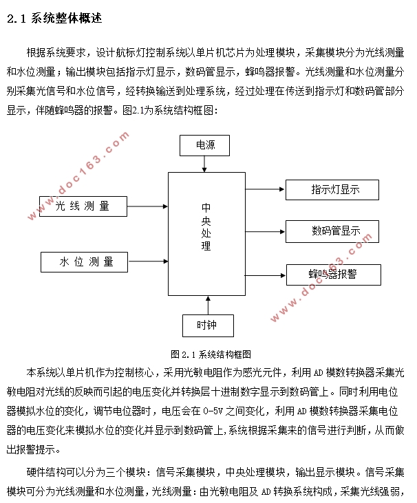
根据系统要求,设计航标灯控制系统以单片机芯片为处理模块,采集模块分为光线测量和水位测量;输出模块包括指示灯显示,数码管显示,蜂鸣器报警。光线测量和水位测量分别采集光信号和水位信号,经转换输送到处理系统,经过处理在传送到指示灯和数码管部分显示,伴随蜂鸣器的报警。
[来源:http://Doc163.com]

目 录
摘 要 I
ABSTRACT II
第一章 绪论 1
1.1系统背景和意义 1
1.2 航标灯技术现状 1
1.3毕业设计的工作内容 2
第二章 系统硬件电路设计 3
2.1 系统整体概述 3
2.2 中央处理模块 4
2.2.1方案设计选择 4
2.2.2 STC12C5A60S2芯片 4
2.2.3具体电路实现 6
2.3 信号采集模块 6
2.3.1 光线采集电路 7
2.3.2 水位采集电路 7
2.4 输出显示模块 9
2.4.1 指示灯显示电路 9
2.4.2数码管显示电路 10
2.4.3 蜂鸣器报警电路 12
2.5电源模块 13
第三章 系统软件程序的设计 15
3.1整体程序设计方案 15
3.2 A/D信号转换 16
3.3数码管显示程序 17
3.4 蜂鸣器报警程序 17
第四章 系统软硬件调试 19
4.1 系统原理图绘制与软件编写 19
4.2系统调试 19
参考文献 22
致 谢 23
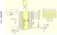
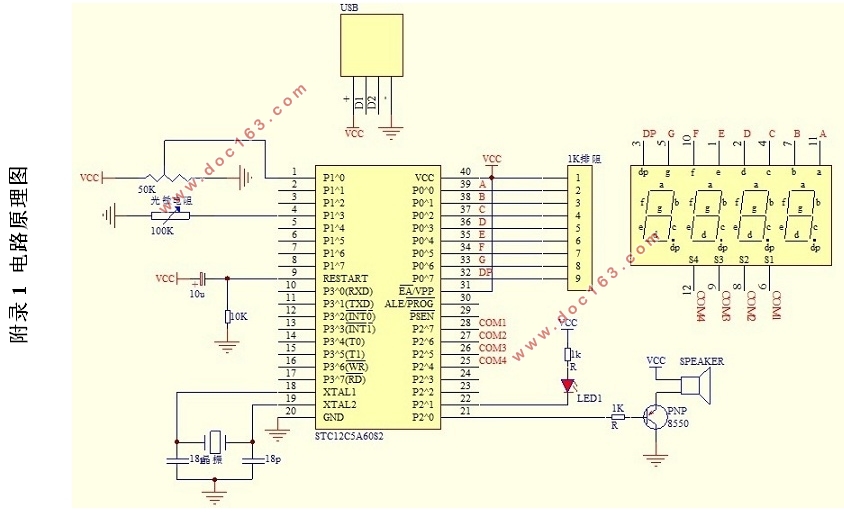
附录1 电路原理图 24 [资料来源:http://Doc163.com]
附录2 程序源代码 25
[来源:http://www.doc163.com]