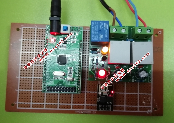
基于STM32单片机和WIFI模块的智能电表设计(附总电路图,实物图)
基于STM32单片机和WIFI模块的智能电表设计(附总电路图,实物图)(课题说明书,开题报告,中期检查表,论文8000字)
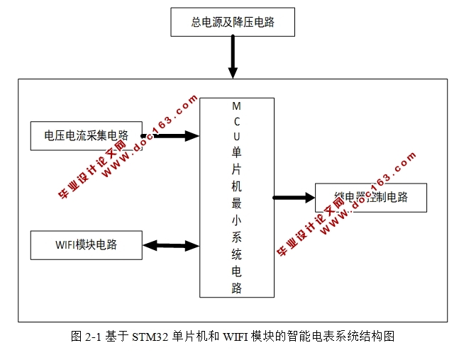
摘 要 伴随着电力系统的电使用量的不断增大以及电压的运行等级日益提升,老的电力使用量的检验测量系统就显露出多种弊端,无法满足现代智能电网趋向数字化的、自动化的需求。本设计是由STM32单片机中的降压芯片给输入电压5V降压为3.3V,给单片机供电,再通过交流电压电流互感模块互感成低压电流,通过电容的整流滤波再通过单片机的采集,进行运算倍数,通过作为热点的WIFI模块输出最后的数值并显示,满足现代化需求。如果说当设备的运行的功率值大于200W时,继电器就能够实现自动的切断电源,不再运行;然而当设备运行的功率小于等于200W时,可以通过手动控制继电器的开关,从而保证用电安全。
关键词 无线通信; 智能电表; 智能电网; 单片机
Simulation of Intelligent Electric Meter Based on STM Single Chip Computer and WIFI Module
Abstract With the continuous increase of the power consumption of the power system and the increasing level of voltage operation,the old inspection and measurement system of power usage has revealed many disadvantages, which cannot meet the needs of modern smart power grid towards digitalization and automation. This design is based on the step-down chip in STM32 microcontroller to provide the input voltage of 5V to 3.3V,to power a microcontroller, and then through the alternating voltage current mutual inductance module into low voltage current, through the capacitor rectifier filter and then through the single-chip acquisition, the operation times, output and display the final value through the WIFI module as the hotspot, meet the needs of modernization. If the operating power value of the equipment is greater than 200W, the relay can automatically cut off the power supply and stop running; However, when the operating power of the equipment is less than or equal to 200W, the switch of the relay can be manually controlled, so as to ensure the safety of electricity. [资料来源:www.doc163.com]
Keywords Wireless communication; Smart meter; Smart grid; Single chip microcomputer
智能电表仿真系统的总体设计
3.1 智能电表系统的硬件设计
3.1.1 STM32单片机核心电路设计
STM32系列处理器的选用是由于本次毕业设计是在所需要实现的功能的前提下能够提供更好的接口,以及可以实现的功能,为实验系统各个功能设计所需的外围扩展电路提供便利[9]。STM32的优点分为以下几个方面:一是拥有Cortex-M3内核,二是具有非常好的实时显示性能并且功耗控制能力强,能够最大程度的集成整合,非常容易开发等。
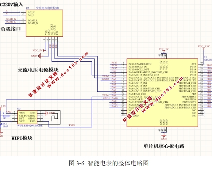
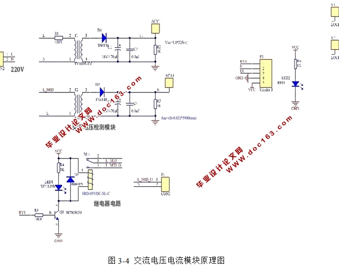
STM32单片机是有很多的优点,51单片机已经落后。相比较而言,STM32单片模块机中包含随机数发生器、电量计量芯片、DSP处理器等,其中多个模块可以进行电参数信号处理,从而通过开启ADC,最终读取ADC转换值,得到数值。STM32单片机的各管脚电路图和核心板内部电路图
[资料来源:www.doc163.com]
[资料来源:http://www.doc163.com]
目 录
摘要及关键词 1
1 绪论 1
2 智能电表仿真方案设计 2
2.1 无线通信技术定义及分类说明 2
2.2 设计方案 3
3 智能电表仿真系统的总体设计 4
3.1 智能电表系统的硬件设计 4
3.2 智能电表系统的软件设计 9
4 系统模拟仿真、测试及分析 10
4.1 电路焊接 10
4.2 系统调试 11
4.3 实物测试 13
5 结论 13
参考文献 14
致谢 16 [资料来源:http://www.doc163.com]
