底板塑料模具设计(含CAD零件图装配图)

资料介绍:
底板塑料模具设计(含CAD零件图装配图)(论文说明书13000字,CAD图16张)
摘 要
注塑模具是现在所有塑料模具中使用最广的模具,能够成型复杂的高精度的塑料制品。本课题是对产品进行模具设计并分析加工工艺。
本模具考虑到年产量、工厂的设备及塑件的精度要求,选择一模两腔结构。以制品的中间水平面为分型面,使制品顺利脱模。主流道采用带Z形头拉料杆的冷料穴,脱模时方便将主流道凝料和塑件带出。分流道采用平衡对称式分布, 确保熔融塑料几乎能同时到达每个型腔的进料口。为了使动、定模能够准确地动作, 导向定位机构利用导柱与导套的配合。顶出机构是推杆推出的一次脱出机构。考虑到零件的位置关系,冷却水道采用循环式分布,以便冷却均匀、快速。
采用PROE来实现产品的三维设计及模具成型零件设计,分析制件的成型质量和完成分型面的设计,再采用组件来实现模架的装配,并在产品设计及模具装配过程中,辅助以必要的理论计算,将数字化设计与理论计算结合起来,可以大大缩短产品研发周期、模具设计周期,提高产品设计及模具设计的准确性、产品成型质量,降低产品研发、模具设计成本。在设计过程中制定了合理的工艺方案,满足了大批量生产要求。同时,还编制了详细的工艺文件来保证模具的顺利加工及制品的生产。
[来源:http://www.doc163.com]
关键词:注塑模具 加工工艺分析 PROE
The bottom of plastic mold design
Abstract
Injection mold is now the most widely used in plastic mold, capable of forming complex precision plastic products. This topic is design the mold of the product and analysis the process.
Considering the annual output, the equipment of the factory and the requirement of precision of the plastic product, the mold chooses a mold two cavity structure. Using the intermediate level of the product as the parting surface is to make the product successful demoulding. Mainstream Road uses cold cave with Z type pulling rod , which is convenient to the mainstream condensate and plastic parts is expected to bring out when demoulding. Subchannel uses balanced and symmetrical distribution, ensure that melting plastic can almost reach the cavity of each feed at the same time. In order to make the movable mould and the fixed mould to accurately action, guide positioning institutions uses positioning guide post and the guide sleeve. The ejection institutions is a extrusion mechanism which is launched by push rod. Considering the relationship between the location of parts, the cooling channel uses circular distribution, in order to make the cooling uniform and fast. [资料来源:https://www.doc163.com]
Using PROE to achieve three dimensional design of product and molding parts design, analysis the quality of forming parts and complete the design of parting surface, then use components to achieve the mold assembly , and in product design and mold assembly process, auxiliary to the necessary calculation, make digital design and theory of computation together, can greatly shorten the the product development cycle, the mold design cycle, improve the accuracy of product design and mold design, product forming quality, reduce the cost of product development and mold design. In the design process the reasonable process has made,met the requirements of mass production. At the same time, also prepared a detailed document of the process to ensure the smooth processing and mold production.
Keywords: injection mold; process analysis; PROE
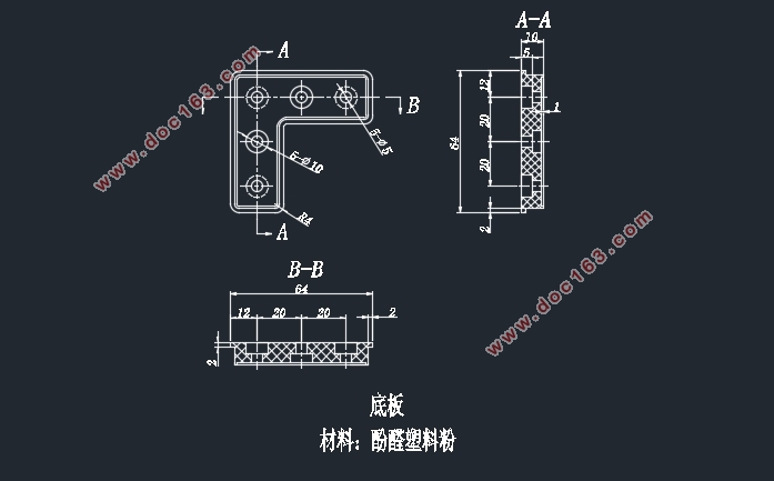
名称:底板
材料:酚醛塑料粉
数量:大批量生产
2.1.1 塑料材料特性
酚醛塑料(phenolic plastics)是以酚醛树脂为基材的塑料,是一种硬而脆的热固性塑料,俗称电木粉,机械强度高,坚韧耐磨,尺寸稳定,耐腐蚀,电绝缘性优异。酚醛塑料是极性聚合物,由于酚羧基的存在,因此它耐酸不耐碱,交联程度不高时碱可解聚。PF固化后优异的机械性能,强度高,坚硬耐磨,尺寸稳定性好,不易变形,PF有较高的绝缘电阻和介电常数,是一种优良的电绝缘材料,PF没有明确的熔点,可在一定范围内软化或者熔化,能溶于酒精、丙酮、苯、甲苯等溶剂,不溶于植物油和矿物油,不含填料的PF几乎不受无机酸的侵蚀,但不耐浓硫酸、浓硝酸、高温铬酸的侵蚀,PF有较高的耐热性加入填料后其耐热性还会提高[3]。 [资料来源:www.doc163.com]
本产品是以酚醛树脂为基材,木粉和矿物为填料制成热固性模塑料,该产品具有较高的电气性能和机械性能,适用于制作低压电器和仪表外科及一般的绝缘结构件[2]。
[版权所有:http://DOC163.com]


目录
摘 要 I
Abstract II
[来源:http://www.doc163.com]
第一章 引言 1
1.1 模具在加工工业中的地位 1
1.2 模具的发展趋势 1
1.2.1 加深理论研究 2
1.2.2 高效率、自动化 2
1.2.3 大型、超小型及高精度 2
1.2.4 革新模具制造工艺 2
第二章 塑件的工艺性分析 3
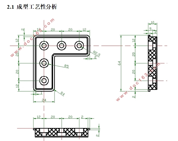
2.1 成型工艺性分析 3
2.1.1 塑料材料特性 4
2.1.2 塑件原材料成型性能 4
2.2 塑料成型工艺参数的确定 4
2.3 计算塑件的体积和质量 5
第三章 模具结构设计 6
3.1确定型腔数目及布置 6
3.2 确定分型面 7
3.2.1分型面的选择原则 7
3.3 确定浇注系统 8
3.3.1主流道的设计 8
3.3.2 冷料穴的设计 9
3.3.3 分流道的设计 10
3.3.4 浇口的设计 10 [资料来源:http://Doc163.com]
第四章 确定型腔的配置 13
4.1 模具成型零件工作尺寸的计算 13
4.2 成型件刚度强度计算 15
第五章 确定脱模方式 16
5.1 模机构的设计原则 16
5.2 模力的计算 16
第六章 推出机构 18
6.1 推出机构原则 18
6.2 推杆机构 18
6.3 推杆与推杆固定板的连接方式 19
6.4 复位杆 19
第七章 温度调节系统 20
7.1 温度调节对制品质量的影响 20
7.2 冷却系统的设计 20
第八章 确定凹模与型芯的结构与固定方式 22
8.1 凹模选用整体组合式 22
8.1.1 一模多腔的型腔尺寸 22
8.2 型芯结构设计 22
8.3 成型部件的固定 23
第九章 导向定位机构设计 24
9.1 导柱导向机构 24
[资料来源:http://Doc163.com]
9.1.1 导柱 24
9.1.2 导向孔 24
9.2 支承零部件设计 26
9.2.1.固定板 26
9.2.2.垫板 26
9.2.3.模板 26
9.2.4.支承板 26
9.2.5. 支架 26
9.2.6 弹簧的选用 27
第十章 确定排气方式 28
第十一章 注塑机参数校核 29
11.1 注射量的校核 29
11.2 锁模力的校核 29
11.3 最大注射压力的校核 30
第十二章 注射机安装模具部分尺寸校核 31
12.1模具厚度 31
12.2模具的长度与宽度 31
12.3开模行程的校核 31
第十三章 绘制模具总装图 32
结语 33
参考文献 34
致谢 35
[资料来源:Doc163.com]
