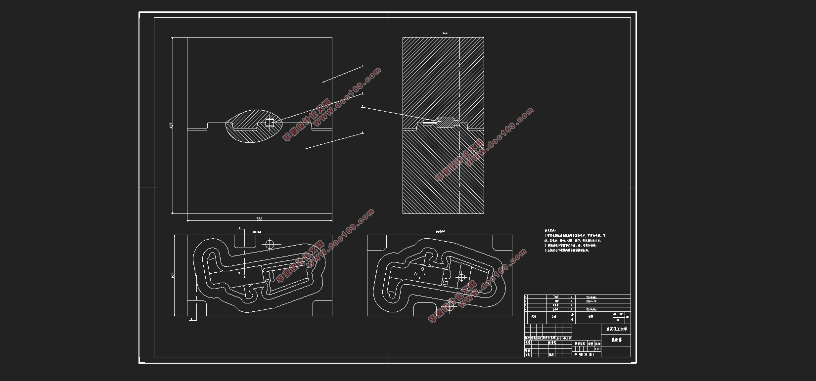
某机匣产品锻造模具的三维设计及有限元分析(含CAD图,STP三维图)

某机匣产品锻造模具的三维设计及有限元分析(含CAD图,STP三维图)(任务书,开题报告,外文翻译,论文说明书15000字,CAD图5张,STP三维图)
摘要
武器轻量化是当今军事装备发展的一个重要方向,而高强铝合金在满足强度的同时质量轻,因此得到广泛的应用。变形铝合金采用塑性工艺(如锻造、挤压)成形,产品组织致密,力学性能较好。随着计算机技术的快速发展,CAD/CAE技术不断应用到工程设计中,锻造模具的三维设计及有限元分析为锻造技术朝着优质轻量化、大型整体化、功能梯度化、精密净形化,高效低成本化和多科学复合化的方向发展作出巨大贡献。锻造过程有限元仿真技术能够通过预测不同工艺参数下坯料的成形过程,从而优化锻造过程,提高锻件质量,缩短开发周期。
本文依据某公司机匣产品进行锻造模具的三维设计。首先通过对机匣的外形进行工艺性分析,选择螺旋压力机上模锻工艺方式;然后通过分析机匣零件形状与计算设计锻件形状,包括锻件的分模面的位置,公差,模锻斜度和圆角半径等;再根据锻件形状确定模具模膛形状,通过查询手册与计算确定锻模飞边槽设计和锻模锁扣设计,并使用CATIA软件建立三维模型;接下来借助锻造CAE软件Deform对锻造过程进行有限元模拟仿真,通过设定不同锻造温度和上模具下压速度进行多次仿真,再通过比较多次仿真结果得出最佳的工艺参数(上模具下压速度150mm/s,锻造温度470 ),以供实际生产过程借鉴与参考。
[资料来源:http://Doc163.com]
关键词:锻造模具、模具设计、三维模型、有限元仿真
Abstract
The light weight of weapon is an important direction in the development of military equipment today, while the high strength aluminum alloy has been widely used for its low quality and low quality. The deformation aluminum alloy adopts plastic technology (such as forging, extrusion) forming, the product organization is dense, the mechanical property is better. With the rapid development of computer technology, CAD/CAE technology is applied to engineering design, continuously forging mould 3 d design and finite element analysis for forging technology towards lightweight, large-scale integration, functional gradient, net shape precision, high efficiency and low cost more to make a huge contribution to the development of science and points out direction. The finite element simulation technology of forging process can optimize the forging process, improve the forging quality and shorten the development cycle by predicting the forming process of billets under different process parameters. [资料来源:http://www.doc163.com]
In this paper, the 3d design of forging die is carried out according to a company's casing product. Firstly, through the process analysis of the shape of the casing, the method of die forging on the screw press was selected. Then the shape of the box part and the shape of the forgings are analyzed, including the position of the parting surface of the forgings, the tolerance, the Angle of die forging, the radius of the circle, etc. According to the shape of the forging mould, the shape of the mold is determined, and the design of the forging die and die lock is determined through the query manual and calculation, and the 3d model is built by using CATIA software. Next with the aid of forging CAE software Deform to simulate the forging process of the finite element simulation, by setting different forging temperature and the upper mold press speed many times simulation, and then by comparing the simulation results obtained many times the best process parameters (mold press speed 150 mm/s, forging temperature, 470), to provide reference for the actual production process with reference.
[资料来源:Doc163.com]
Key Words: Forging die; mold design; 3d model; finite element simulation.
课题研究内容与目标
本文的研究内容包括介绍当前世界各国材料成型工艺技术研究背景、研究现状和发展趋势,并对某公司机匣产品进行其的锻件和锻造模具三维设计,其中包括对锻件的分模位置,锻件公差,模锻斜度,圆角半径的确定与建立三维模型,在设计完锻件后,将对锻造模具的飞边槽,锁扣,模膛进行设计与建立三维模型。接下来本文将介绍锻造过程的有限元仿真,从锻造有限元仿真的原理开始,然后通过Deform软件仿真机匣锻件的锻造过程,包括前处理中的网格划分,工艺参数设定,摩擦接触定义等步骤,还要通过分析比较仿真结果得出最佳工艺参数组合,以达到降低生产成本,提高锻件质量的目的。
2.1零件工艺性分析
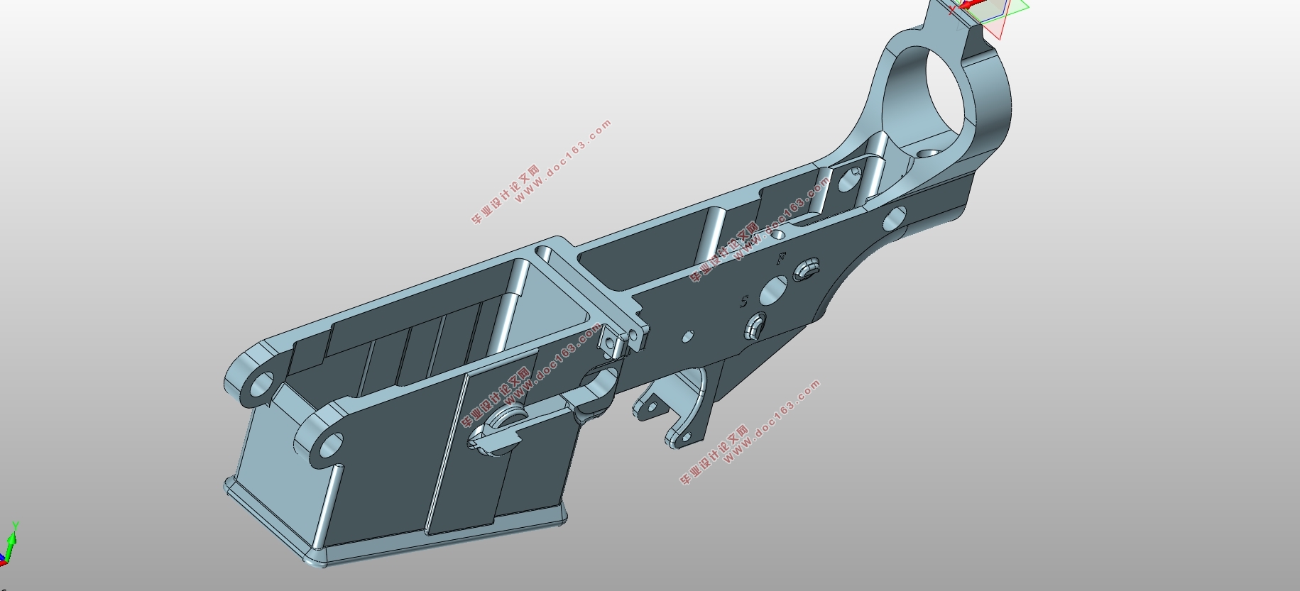
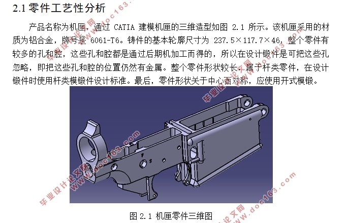
产品名称为机匣,通过CATIA建模机匣的三维造型如图2.1所示。该机匣采用的材质为铝合金,牌号是6061-T6。铸件的基本轮廓尺寸为237.5×117.7×46,整个零件有较多的孔和腔,这些孔和腔都是通过后期机加工而得的,所以在设计锻件是可把这些孔忽略,即把这些孔和腔的位置仍然有金属。整个零件形状较长,属于杆类零件,在设计锻件时使用杆类模锻件设计标准。最后,零件形状关于中心面对称,应使用开式模锻。 [资料来源:http://www.doc163.com]
[来源:http://Doc163.com]


 [来源:http://Doc163.com]


[资料来源:https://www.doc163.com]
目录
第1章 绪论 1
1.1课题研究的背景及意义 1
1.1.1金属塑性加工 1
1.1.2模具 1
1.1.3铝合金锻件 1
1.1.4锻造加工过程有限元仿真模拟的意义 2
1.2国内外研究现状 2
1.2.1锻造的发展现状与趋势 2
1.2.2锻造有限元仿真的发展现状与趋势 3
1.3课题研究内容与目标 3
第2章 某机匣产品锻造模具设计 5
2.1零件工艺性分析 5
2.2锻件图设计 5
2.2.1确定分模面位置和形状 5
2.2.2确定锻件公差和机械加工余量 6
2.2.3确定模锻斜度 7
2.2.4确定锻件的圆角半径 8
2.3锻造模具的设计 8
2.3.1终锻型槽的设计 8
2.3.2螺旋压力机吨位的选择 9
2.3.3飞边槽的设计 10
[来源:http://Doc163.com]
2.3.4锁扣的设计 11
第3章 锻造过程有限元仿真的基础与理论 12
3.1锻造过程有限元数值分析法 12
3.2锻造过程有限元仿真原理 12
3.2.1刚塑性有限元法基本假设 12
3.2.2刚塑性变分原理 13
3.3刚塑性有限元模拟的实质 13
第4章 某机匣产品锻造过程的有限元仿真 15
4.1 Deform软件介绍 15
4.2 Deform模拟分析 15
4.2.1模拟方案设计 15
4.2.2模拟过程 16
4.3模拟结果分析 22
4.3.1上模具下压速度的影响 22
4.3.2锻造温度的影响 24
第5章 总结与展望 27
参考文献 28
致谢 30
上一篇:锥齿轮成型工艺及模具设计(含CAD零件图装配图,UG三维图,deform模拟)
下一篇:机械人体秤功能零件主槽B的模具设计(含CAD零件装配图,UG三维图)
