锥齿轮成型工艺及模具设计(含CAD零件图装配图,UG三维图,deform模拟)

锥齿轮成型工艺及模具设计(含CAD零件图装配图,UG三维图,deform模拟)(任务书,开题报告,外文翻译,论文说明书14000字,CAD图9张,UG三维图)
摘要
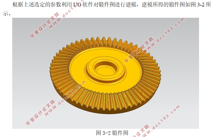
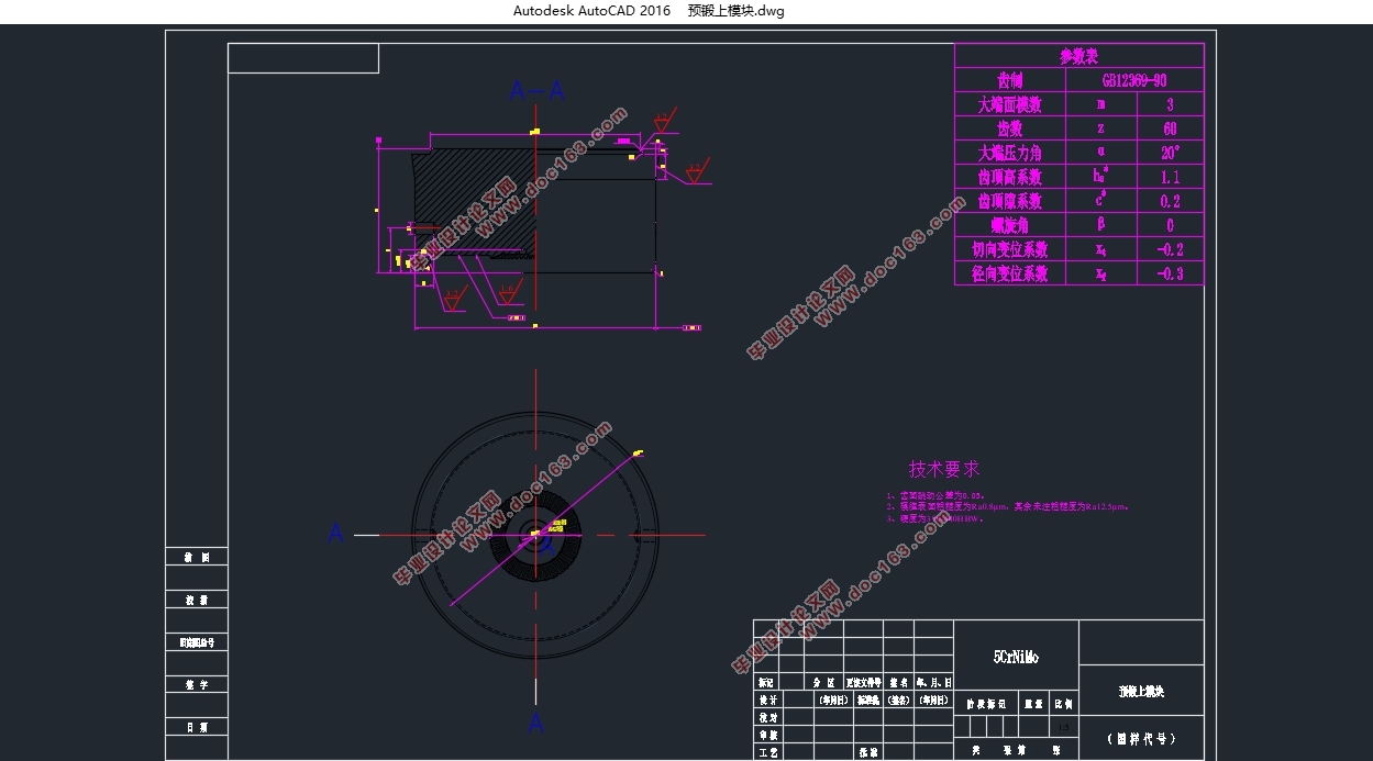
直齿锥齿轮是一种广泛应用于汽车,船舶,机床等工程领域的重要零部件,利用模锻工艺制造直齿锥齿轮相比于其他制造工艺不但可以提高材料的利用率,节省成本,提高生产效率等还可以使锥齿轮获得更好的力学性能和更长的使用寿命。鉴于以上的优点,锥齿轮的模锻工业化生产在国内已经非常普遍。本设计通过直齿锥齿轮的零件图确定了模锻分为制坯,预锻,终锻三个工步并设计出锻件图,然后计算出毛坯的尺寸,计算成形力,选择合适的成形设备,接着设计出终锻模膛和预锻模膛,然后使用UG建模软件对模膛进行建模,利用deform软件对制坯,预锻,终锻进行有限元模拟分析,通过分析修改工艺方案和工艺参数,然后进行模块及模架的设计。
关键词:直齿锥齿轮;锻件图;有限元模拟;模块及模架设计
Abstract
Straight bevel gear is a kind of important component widely used in automobile, ship, machine tool and other engineering fields. The use of die forging process to manufacture beveled bevel gear can not only improve the utilization rate of materials, but also save costs, compared with other manufacturing processes. Production efficiency can also enable bevel gears to achieve better mechanical properties and longer service life. In view of the above advantages, industrial production of bevel gear forging has become very common in China. In this design, the die forging is divided into three steps of blank making, pre-forging and final forging through the parts drawing of the straight bevel gear, and the forging drawing is designed. Then the size of the blank is calculated, the forming force is calculated, and the suitable forming equipment is selected. Then, the final forging die and the forging die were designed. Then the die was modeled using the UG modeling software. The finite element simulation analysis was performed on the blanks, pre-forging and final forging using the deform software, and the process plan was modified through analysis. And process parameters, then the design of the module and mold frame. [来源:http://www.doc163.com]
Key Words:straight bevel gears; forging drawings; finite element simulation; module and formwork design
[版权所有:http://DOC163.com]


目录
摘要 Ⅰ
[资料来源:https://www.doc163.com]
Abstract Ⅱ
第1章绪论 1
1.1设计目的及意义 1
1.2直齿锥齿轮的成型工艺现状 1
1.3齿轮锻造国内外研究现状 2
第2章直齿锥齿轮的模锻工艺设计 4
2.1 工艺方案的分析、比较与确定 4
2.2锻件图设计 4
2.2.1确定分模位置 5
2.2.2模锻件的加工余量和公差 5
2.2.3模锻斜度及圆角半径 6
2.2.4冲孔连皮 6
2.2.5技术条件 6
2.2.6绘制锻件图 7
2.3模锻工步的选择 7
2.4毛坯尺寸的确定 7
2.5模锻设备及其吨位的选取和设备型号的选择 8
2.5.1成形设备的选择 8
2.5.2设备吨位的确定 10
2.5.3设备型号的选择 11
2.6模膛设计 11 [版权所有:http://DOC163.com]
2.6.1终锻模膛设计 11
2.6.2预锻模膛设计 12
2.6.3制坯模膛设计 12
第3章有限元模拟分析 13
3.1DEFORM软件介绍 13
3.2制坯模拟 13
3.3预锻过程模拟分析及工艺参数的修改 13
3.4终锻过程模拟分析及工艺参数的修改 19
第4章模块与模架设计 22
4.1模块设计 22
4.2模架设计 22
第5章结论 27
参考文献 28
致谢 29 [来源:http://Doc163.com]
上一篇:拨头成型工艺及模具设计(含CAD零件图装配图,PROE三维图)
下一篇:某机匣产品锻造模具的三维设计及有限元分析(含CAD图,STP三维图)
