汽车座椅连接件冲压成形工艺分析及模具设计(含CAD图,SolidWorks三维图)

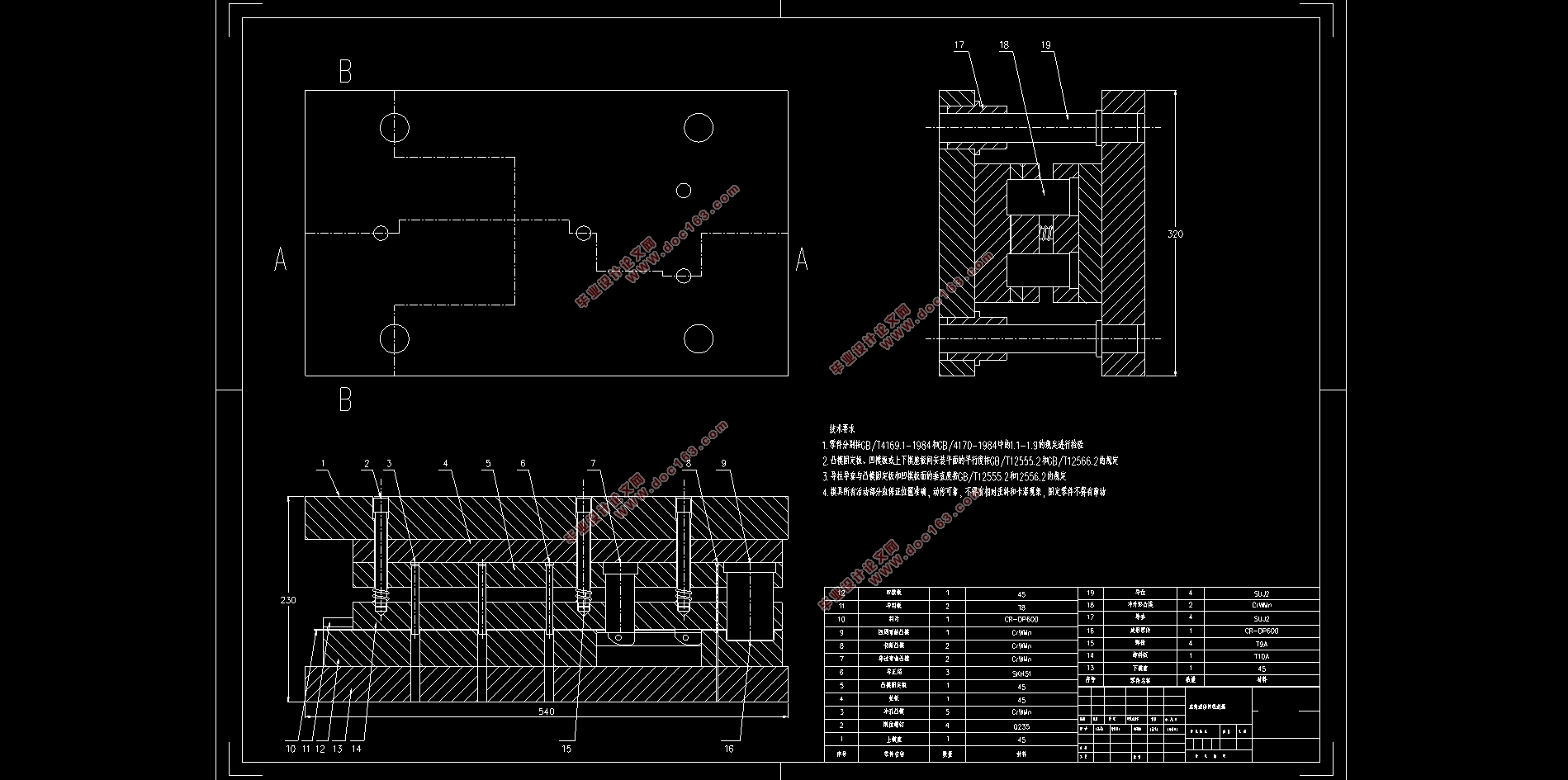
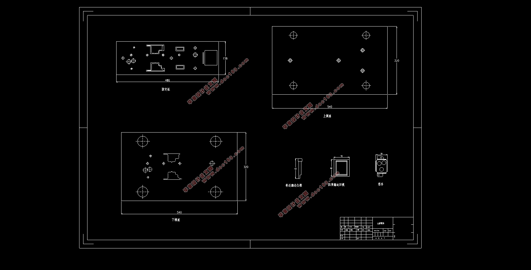
汽车座椅连接件冲压成形工艺分析及模具设计(含CAD图,SolidWorks三维图)(任务书,开题报告,外文翻译,论文说明书16000字,CAD图2张,SolidWorks三维图)
摘要
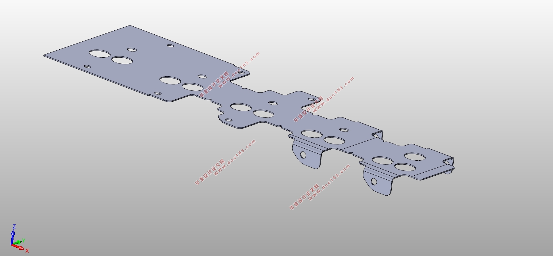
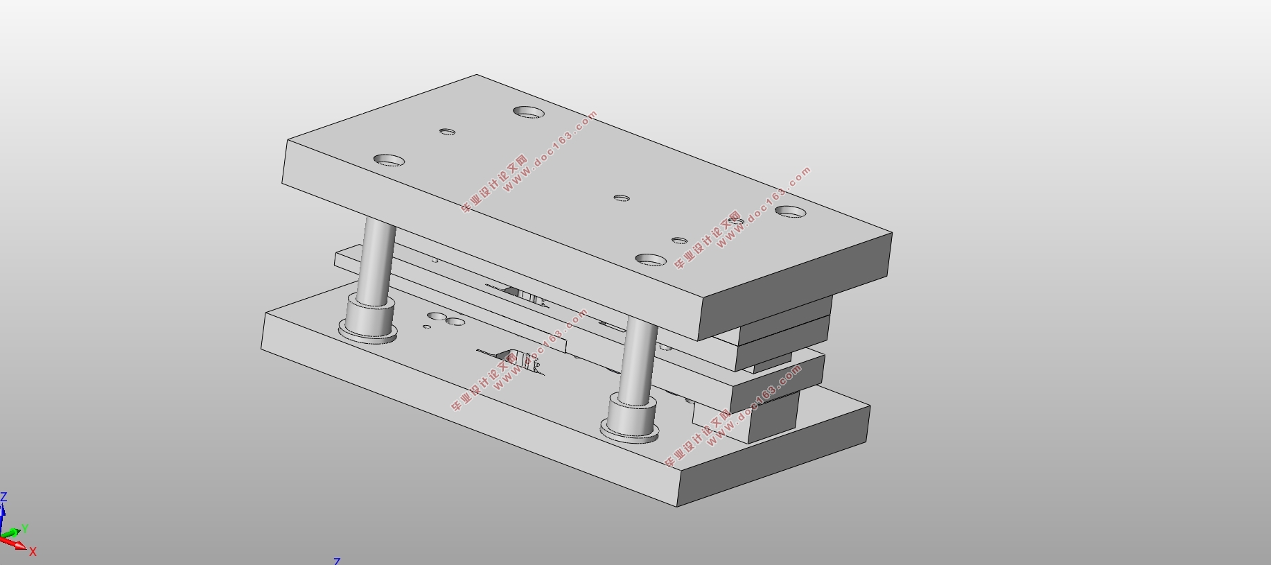
本论文针对汽车座椅连接件冲压成形工艺及模具设计而展开。首先分析座椅连接件模型形状和尺寸参数,根据设计经验初步确立大致工艺方案,并选择几种材料以备选用。通过AutoForm软件对汽车座椅连接件的翻边和冲孔加工进行数值模拟,验证成形方案可行性并优化冲压成形工艺参数,利用回弹补偿进一步降低回弹值。对模具所受弯曲力、顶件力等进行具体计算。结合冲压成形工艺要求和模具受力情况,完成压力机的选型、凸凹模间隙的计算以及冲裁模和弯曲模每一工位的模具刃口尺寸计算。最后确立模具闭合高度,选取模架、模座、导套和模具材料,设计凸凹模固定形式、定位部件和卸料装置。
关键词:连接件 冲压成形 回弹补偿 模具设计
ABSTRACT
This paper is aimed at the stamping forming process and mold design of automobile seat connecting parts.Firstly,the shape and size parameters of the seat connector model are analyzed.According to the design experience, the rough process plan is initially established, and several materials are selected for use. Then, the AutoForm software is used to simulate the flanging and punching of the car seat connector, verify the feasibility of the forming scheme and optimize the stamping process parameters,and use the springback compensation to further reduce the rebound value.The bending force and the top piece force of the mold are specifically calculated. Combined with the requirements of stamping forming process and the force of the mold,the selection of the press,the calculation of the gap between the convex and concave molds,and the calculation of the die edge size of each station of the blanking die and the bending die are completed.Finally,the mold closing height is established, the mold base,the mold base,the guide sleeve and the mold material are selected,and the convex and concave mold fixing form,the positioning component and the unloading device are designed. [资料来源:https://www.doc163.com]
Key words: connector;stamping simulation;springbucks compensation;mold design
[资料来源:www.doc163.com]
 [版权所有:http://DOC163.com]

目录
摘要 I
目录 III
第1章 绪论 1
1.1 研究背景与意义 1
1.2 国内外研究现状 1
1.3 论文主要研究内容 2
第2章 工艺分析及总体方案设计 3
2.1 座椅连接件三维参数 3
2.2 材料选择 3
2.3 方案设计 4
2.4 本章小结 5
第3章 AutoForm数值模拟 7
3.1 初次模拟计算 7
3.2 回弹补偿 8
3.2.1 工艺参数优化 9
3.2.2 型面结构优化 15
3.3 本章小结 17
第4章 排样设计及模具受力计算 18
4.1 排样设计 18
4.2 弯曲力计算 20
4.3 冲裁力计算 20
4.4 卸料力与顶件力计算 21
4.5 模具压力中心计算 22
4.6 压力机选择 23
4.7 本章小结 24
第5章 模具工作部分设计计算 25
5.1 凸凹模间隙 25
5.1.1 冲裁模间隙 25
5.1.2 弯曲模间隙 25 [资料来源:Doc163.com]
5.2 冲裁模刃口尺寸计算 26
5.2.1 第一工位刃口尺寸计算 29
5.2.2 第二工位刃口尺寸计算 31
5.2.3 第四工位刃口尺寸计算 32
5.3 弯曲模刃口尺寸计算 32
5.3.1 第三工位刃口尺寸计算 33
5.3.2 第五工位刃口尺寸计算 33
5.4 本章小结 34
第6章 模具结构设计 35
6.1 模具闭合高度的确定 35
6.2 模架的选用 35
6.3 模座及导套的选取 36
6.4 冲裁和翻边凸凹模结构设计 37
6.4.1 模具材料选择与热处理 37
6.4.2 各凸凹模的固定形式的设计 37
6.5 定位零件的设计 38
6.6 卸料装置的设计 38
6.7 模具工作原理 38
6.8 本章小结 40
第7章 模具报价 41
7.1 报价方法 41
[版权所有:http://DOC163.com]
7.2 报价计算 41
7.3 本章小结 42
第8章 总结与展望 43
8.1 总结 43
8.2 展望 43
参考文献 45
致谢 47 [资料来源:www.doc163.com]
上一篇:汽车车身内衬板冲压成形工艺分析及模具设计(含CAD图)
下一篇:叉形支座注塑成形工艺与模具设计(含CAD零件图装配图)
