液压金属打包机设计(含CAD零件装配图,Proe三维图)

液压金属打包机设计(含CAD零件装配图,Proe三维图)(任务书,开题报告,论文说明书14000字,CAD图10张,Proe三维图)
摘 要
随着人类科技的飞速发展,金属资源对于各国来说也变得越加重要。对现有的金属资源的过渡开采和不合理使用的,造成了大量的金属浪费。这自然而然的引起了人们的担忧,因而,废金属的回收再利用的课题也成了工业发展中必不可少的研究方向。
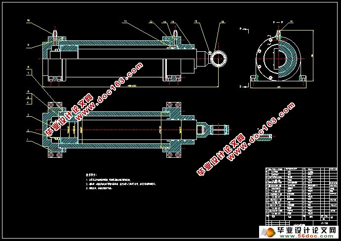
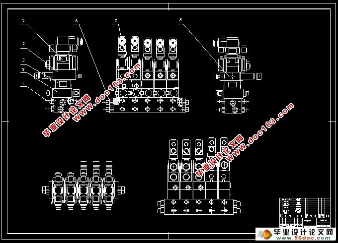
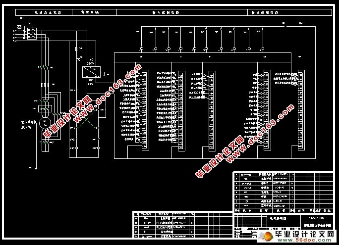
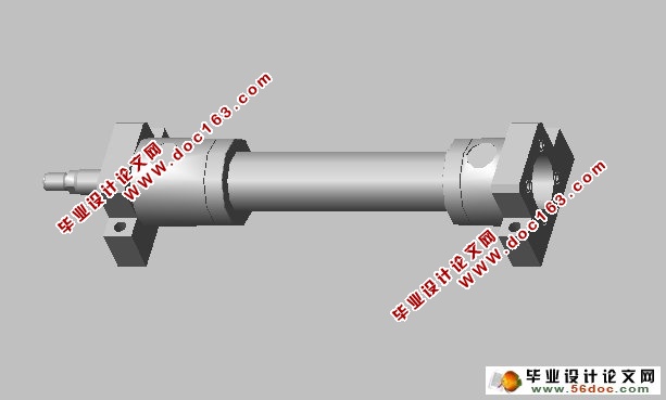
本设计的主要内容是液压缸和机构的设计、选型,金属打包机液压原理图,电气原理图以及叠加阀的设计、选型。本设计中,主、侧液压缸为打包机提供压缩动力,替代了传统的丝杆。主液压缸安置在压缩室后端面,侧压缸安置在压缩室左侧面。液压缸的设计包括了缸筒、活塞、导向套、活塞杆等的设计计算,以及密封圈、防尘圈、活塞与缸筒、活塞杆密封方式的选型。压缩室的设计主要是用来确定尺寸大小并且对其强度校核。本金属打包机除了主、侧液压缸外,还有上盖、锁紧机构、前门三个辅助液压缸,它们分别控制着上盖的闭合、锁紧机构的进退、前门的开合。
本设计完成了上述液压缸和机构的设计、选型,金属打包机液压原理图、电气原理图以及叠加阀设计选型。整个打包机不但制造成本低,而且企业的广泛需要,拥有很好的市场前景。
关键词:废金属的回收、金属打包机、液压
ABSTRACT
With the rapid development of science and technology, industrial production has become an inevitable trend of the development of automation. Metal resources is also becoming increasingly important for countries. The transition of the existing metal resources mining and unreasonable use of, and are responsible for a large number of metal waste. This naturally caused concern, therefore, scrap metal recycling project has become essential to industrial development and the research direction. The design of the hydraulic metal baling press use hydraulic pressure to compress with packaging, metal scrap has a certain size, convenient transportation, recycling and recycled scrap metal, in order to put into production again. So greatly improve the utilization rate of the metal, the process of the waste is in a certain extent, ease the intense demand for metal resources.
The main content of this design is the design of the hydraulic cylinder and institutions, selection, metal baling press hydraulic principle diagram, electrical principle diagram and superposition valve design, type selection. In this design, the main hydraulic cylinder, side provide compression power for packing machine, replacing the conventional screw. The main hydraulic cylinder face after placed in the compression chamber, lateral pressure cylinder placed in the left lateral compression chamber. The design of the hydraulic cylinder includes cylinder, piston, guide sleeve, piston rod etc. The design and calculation, and the sealing ring, dust ring, piston and cylinder, piston rod sealing mode selection. The design of the compression chamber is mainly to determine the size and intensity. This metal baling press in addition to the main hydraulic cylinder, side, and on the cover, locking mechanism, the front three auxiliary hydraulic cylinder, respectively control with lid closed, in a locking mechanism, the front door open and close. And three auxiliary cylinder and the main work, side two cylinder each cross movement.
This design completed the hydraulic cylinder and institutional design, selection, metal baling press hydraulic principle diagram, electrical schematic diagram and superposition valve design selection. Some of its operations to achieve automation, which improve labor efficiency, reduce labor intensity. The baling press not only manufacturing cost is low, and enterprise need to extensively, have good market prospects.
Key words:Scrap metal recycling、Metal baling press、hydraulic pressure
设计内容简介
1.2.1 研究解决的问题
传统的包装机械设备包括传动机构、动力系统以及工作机构。机器运动的能源来自动力系统;而机器的运行是靠传动机构来实现的;然而传动机构的作用是为了让动力源满足运行机构对速度、力、和其他运行功能要求的装置 。
1)初始数据:
(1)公称推力:1150KN
(2)压缩室尺寸:1100×650×550mm
(3)包块尺寸(长×宽×高):(240-350)×250×250mm
(4)包块密度:≥ 1800kg/m3
(5)生产效率:950-1200kg/h [资料来源:http://www.doc163.com]
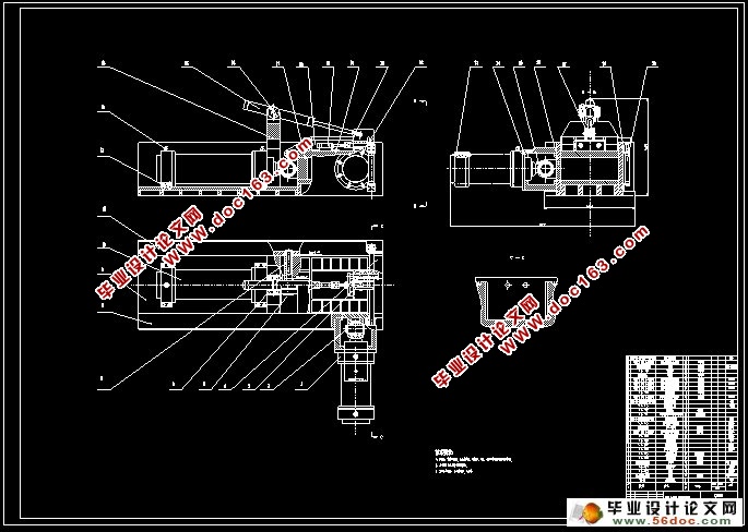
主要任务就是进行打包机的外形设计以及确定辅缸及主缸压包输出包的运作形式,并且对涉及的部位受力分析。
打包机的结构设计
打包机的机体设计最基本的任务就是确定合适的机体结构,并且从初始的数据出发,选择合理的结构和大小,最后设计出符合条件的压缩室。因此,对于液压金属打包机的推送压缩块运做程序的分析,是实现本次设计的必要条件 。
[资料来源:http://www.doc163.com]
 [资料来源:https://www.doc163.com]
目 录
摘 要 I
ABSTRACT II
目 录 III
第1章 引 言 1
1.1 文献综述 1
1.1.1课题研究背景 1
1.1.2 课题研究的意义 2
1.2 设计内容简介 2
1.2.1 研究解决的问题 2
1.2.2整体设计方法 2
1.3 本章小结 3
第2章 打包机主体的设计分析 4
2.1 打包机的结构设计 4
2.1.1打包机的运动 4
2.1.2打包机的总布局 4
2.2 打包机压缩室的设计与强度校核 6 [资料来源:Doc163.com]
2.2.1 压头的强度校核 6
2.2.2 压缩室的设计 6
第3章 打包机液压系统的设计 9
3.1 液压系统的特点 9
3.2 液压系统工况分析 9
3.2.1分析系统工况 9
3.2.2确定液压系统的主要参数 10
3.3 拟订液压系统原理图 11
3.3.1确定供油路线 11
3.3.2液压回路的设计 11
3.3.3 拟订液压系统图 12
3.3.4液压系统原理图的分析设计 12
3.4 液压系统的计算和液压元件的选定 14
3.4.1液压缸的设计计算 14
3.4.2 选择液压元件 19
第4章PLC控制系统设计 23
4.1 PLC控制器的选择 23
4.2 系统控制要求 23
4.3 I/O点数的确定 24
4.4 画电气原理图 24
总 结 26
[资料来源:http://Doc163.com]
参考文献 27
致 谢 28
[资料来源:https://www.doc163.com]
上一篇:切刀下置式莲子剥壳机-剥壳及分离装置设计(CAD,CAXA,零件装配图)
