差动变速器的设计
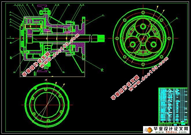
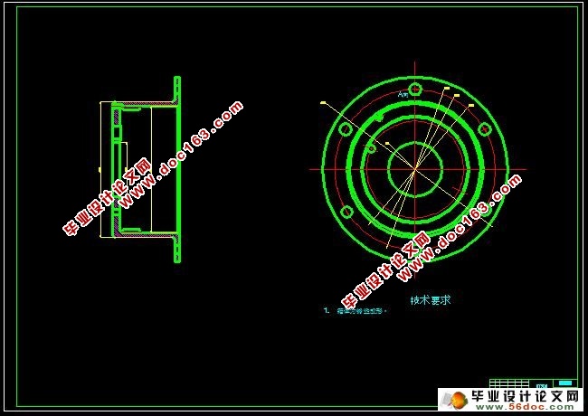
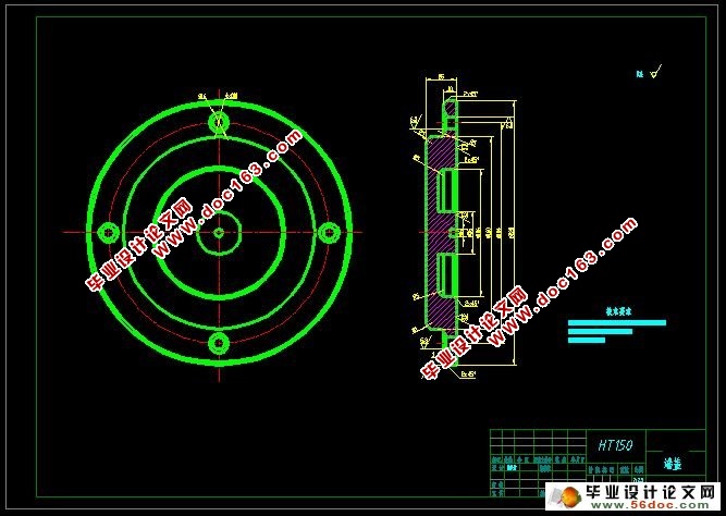
差动变速器的设计(任务书,开题报告,外文翻译,进度计划表,论文说明书13000字,cad图纸4张)
摘 要
差动变速器是由基本型变速器对差动轮系进行封闭而成的一种组合式变速传动装置.基本型变速器一般分为磨擦式、链式、带式和脉动式.通过选取装置内各不同传动参数,可实现精密调速并扩大基本型变速器承载能力,或者扩大基本型变速器的调速范围,甚至实现过零调速.将基本型变速器和差动轮系组合,有利于提高变速器变速范围,因此差动变速器具有很好的开发空间和市场前景。
针对差动变速器的分析和设计较为复杂的问题,提出了一种对差动变速器进行差动轮系的配齿计算方法,以及与变速器的组合装配设计的方法,给出了差动变速器的详细设计过程,并根据参数画出其装配图,为同类型传动设计提供了理论基础和方法。
通过分析差动无级变速器中带式无级变速工作原理,对差动无级变速器中的带轮传动和差动轮系及定轴齿轮副进行计算设计,得到了带轮急齿轮传动的重要参数,最后对其组合装配设计,实现了提高无级变速器的变速范围。
关键词:差动变速器;传动装置;配齿计算;组合设计
Abstract
Differential transmission is composed of basic transmission to closed differential gear train a combination of variable speed drive. Generally divided into basic transmission friction type, chain and belt type and pulsating flow. By selecting device inside the different parameters, which can realize precise control of motor speed and expand the basic transmission capacity, and expand the basic transmission speed range, and even realize zero speed. The basic transmission and the differential gear train, to improve the transmission speed range, as a result, the differential transmission has the very good development space and market prospects.
[资料来源:http://Doc163.com]
According to the analysis of the differential transmission and design of more complex problems, put forward a kind of differential gear train was carried out on the differential transmission of gear calculation method, and combined with the transmission assembly design method, gives the detailed design process of a differential transmission, and draw the assembly drawing, according to the parameters of the same type transmission design provides a theoretical basis and methods.
By analyzing the differential stepless transmission belt type CVT working principle, the differential stepless transmission pulley transmission and the differential gear train and in the calculation and design of fixed axis gear pair, the pulley gear transmission of the important parameters, finally the combination assembly design, realized the stepless transmission speed range.
Key words: differential transmission; Transmission device; For computing tooth; Composite design
1.2 设计任务
确定设计方案;喂料器技术参数的确定;电机参数的确定;调制器技术参数的确定;主传动系统技术参数的确定;主轴刚度的校核计算;环模和压辊配合使用的技术参数的确定,压辊得制作工艺过程;其他相关说明。完成整机的三维设计、主要部件的组装图、重要零件的工程图、相关参数的优化。
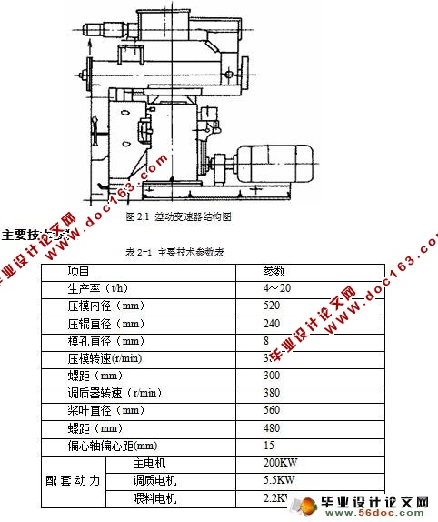
AHHC520型制粒机主要用于中大型配合饲料厂压制颗粒饲料,也可用于机械化养养殖场。该产品可以根据用户的需求,配备不同模孔孔径的压模,生产各种规格的颗粒饲料,从而用于不同的养殖对象。该机喂料、调质、制粒分别采用独立传动,工作可靠。该设备主要组成部分有:喂料系统,调质系统,制粒系统,主传动系统,过载保护系统和润滑系统等。
[来源:http://Doc163.com]

[资料来源:http://doc163.com]
目 录
摘要 III
ABSTRACT IV
目 录 V
1 绪论 1
1.1 设计目的和意义 1
1.2 设计任务 1
2 总体方案设计 1
2.1 主要组成结构 2
2.2 主要技术参数 2
2.3 工作原理与工作过程概述 3
2.3.1 环模制粒机的工作原理 3
2.3.2 环模制粒机的主要工作过程 4
3 喂料机构设计 4
3.1 喂料输送结构设计 5
3.2 喂料器参数计算 5
3.2.1 螺旋直径D与螺旋轴转速n的计算 5
3.2.2 物料轴向推进速度计算 6
3.2.3 电机的选择 6
3.3 机槽的设计 6
4 调制器结构设计 7
4.1 调质的作用 7
4.2 调质过程的控制 7
4.3 调制器总体方案设计及计算 7
5 主传动系统的设计 9
5.1 主电机的选择 9
5.2 主传动计算 9
5.2.1 选定齿轮类型、精度等级、材料及齿数 9
5.2.2 按齿面接触强度设计 9
5.2.3 按齿根弯曲强度设计 11
5.2.4 几何尺寸计算 12
5.2.5 结构设计及绘制齿轮零件图 12
5.3 空心轴的有限元分析 12
6 制粒系统的设计与计算 19
6.1环模的加工工艺综述及结构设计 19
6.1.1 环模的热处理工艺 19
6.1.2 环模模孔的加工工艺 20
[来源:http://www.doc163.com]
6.1.3 环模的结构 20
6.1.4 方案设计 20
6.2 环模的参数计算 20
6.2.1 环模厚度计算 20
6.2.2 环模单位功率面积 20
6.3 压辊的设计计算 21
6.4 环模和压辊工作间隙的调整 21
7 设备拆装及维护 23
7.1 制粒机的使用和维护 23
7.2 制粒机的检修 23
7.2.1 喂料系统拆装 23
7.2.2 主传动系统拆装 24
7.2.3 易损件的拆装 26
8 结论与展望 29
8.1 结论 29
8.2 存在的不足及对未来的展望 29
致 谢 30
参考文献 31 [资料来源:Doc163.com]
上一篇:槽轮间歇回转机构的设计
下一篇:车载式高空作业平台的结构设计
