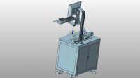
工程装备焊接修复量自动检测系统的开发(含STEP三维建模图,程序代码)

工程装备焊接修复量自动检测系统的开发(含STEP三维建模图,程序代码)(任务书,开题报告,外文翻译,论文说明书21000字,STEP三维图,程序代码)
摘要
在大型装备的定期检修过程中,当装备的机体、主支撑件等尺寸较大或者部件不能拆卸的金属件发生损坏或者故障时,由于其尺寸较大和不便移动的特点,只能在现场进行紧急性维修,主要的维修手段是通过焊接或者堆焊来实现。
本文采用机器视觉的检测方法,设计了一种工程装备修复量检测系统。基于机器视觉的检测装置为修复工作提供工艺参数的方法已经成为现今主流修复方法,具有高精度、高效率的特点,灵活性强,适用于本设计对工程装备修复量的检测工作。本系统采用线激光三维测量技术,结合三角剖分和趋势点提取的方法对修复量进行参数提取和三维重构,可为工程装备修复量检测提供一种可行性方案。
本论文的主要工作包括:
(1)完成了针对工程装备修复量检测系统总体方案设计,从修复量结构特点入手,完成检测方案整体流程设计,从系统标定、图像检测和数据处理等方面开展工作,主要包括工程装备修复量检测系统的整体结构设计、系统流程设计、实验平台硬件选型、软件设计和建模。
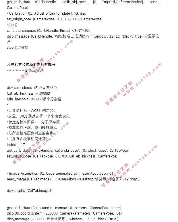
(2)完成了工程装备修复量检测系统的标定和图像处理工作,采用基于Halcon软件平台设计检测系统标定程序和图像处理程序,根据设计要求完成片光标定、相机标定和运动姿态标定程序的开发,针对线激光图像特点,完成图像滤波和光条中心提取程序的开发。 [版权所有:http://DOC163.com]
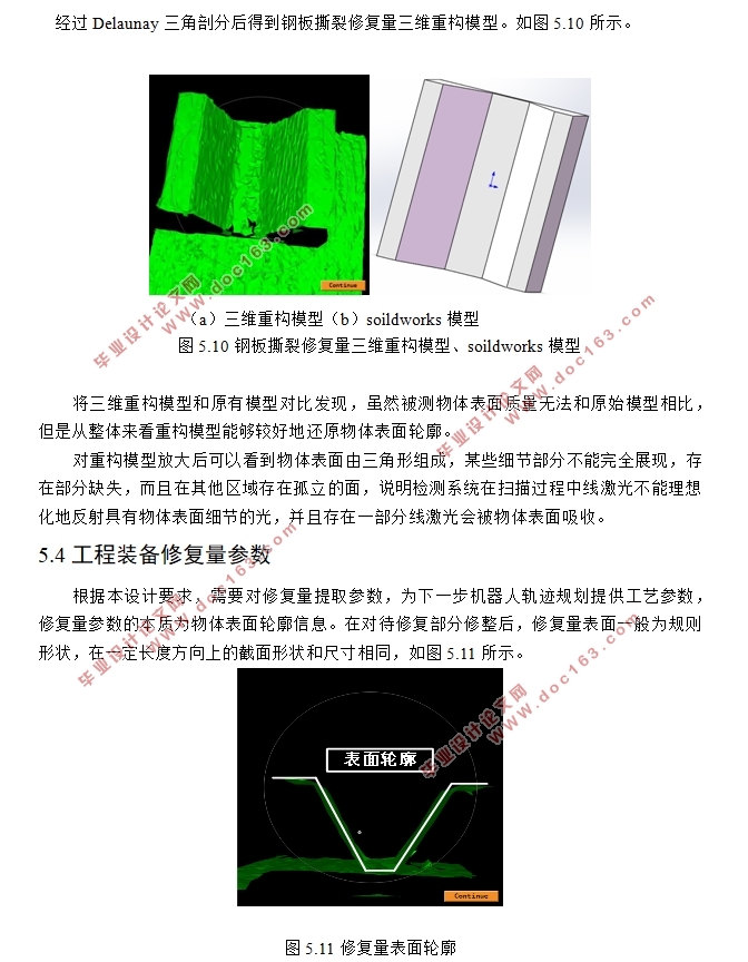
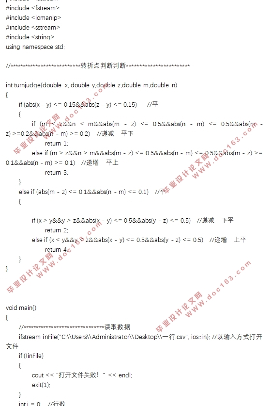
(3)完成了工程装备修复量表面三维重构和修复量参数的算法设计,设计针对点云数据的趋势转折点提取算法,并基于Visual Studio 2017平台完成修复量参数提取软件开发,根据设计要求选择Delaunay三角剖分法作为三维重构算法,基于Halcon软件完成三维重构程序的开发。
(4)完成了工程装备修复量检测系统的实验部分,对选定修复量模型三维检测,采用基于Halcon设计的图像处理软件完成图像处理和三维重构,采用基于C++参数提取软件完成参数提取工作,通过对比原有模型,验证了本文检测系统的有效性。
关键词:工程装备;维修保障;堆焊;三维重构;线激光
Abstract
During the regular maintenance of large-scale equipment, when the size of the equipment, the main support, etc., or the metal parts that cannot be disassembled are damaged or malfunction, due to their large size and inconvenient movement, emergency can only be carried out on site. For maintenance, the main maintenance method is achieved by welding or surfacing.
In this paper, a machine vision detection method is designed to design a repairing system for engineering equipment. The machine vision-based detection device provides the process parameters for the repair work. It has become the mainstream repair method today. It has the characteristics of high precision and high efficiency, and has strong flexibility. It is suitable for the detection of engineering equipment repair volume. The system adopts the line laser three-dimensional measurement technology, combined with the triangulation and trend point extraction method to extract the parameters and three-dimensional reconstruction of the repair quantity, which can provide a feasible solution for the engineering equipment repair quantity detection. [来源:http://www.doc163.com]
The main work of this thesis includes:
(1) Completed the overall scheme design for the engineering equipment repair quantity detection system, starting from the repair quantity structure characteristics, completing the overall process design of the test plan, and carrying out work from system calibration, image detection and data processing, including the repair of engineering equipment. The overall structural design of the inspection system, system flow design, experimental platform hardware selection, software design and modeling.
(2) Completed the calibration and image processing of the engineering equipment repair quantity detection system, and adopted the Halcon software platform to design the detection system calibration program and image processing program, and completed the development of the film cursor setting, camera calibration and motion attitude calibration program according to the design requirements. For the characteristics of line laser images, the development of image filtering and strip center extraction procedures is completed.
(3) The algorithm design of 3D reconstruction and repair parameters of engineering equipment repair surface is completed, the trend turning point extraction algorithm for point cloud data is designed, and the repair parameter extraction software development is completed based on Visual Studio 2017 platform, according to design requirements. Delaunay triangulation is used as a 3D reconstruction algorithm to
develop 3D reconstruction programs based on Halcon software.
(4) The experimental part of the engineering equipment repair quantity detection system was completed. The 3D inspection of the selected repair quantity model was carried out. The image processing software and 3D reconstruction were completed by using the image processing software based on Halcon design. The parameter extraction work was completed based on C++ parameter extraction software. By comparing the original model, the effectiveness of the detection system in this paper is verified.
Keywords: engineering equipment; maintenance support; surfacing; 3D reconstruction; line laser [版权所有:http://DOC163.com]
课题研究基本内容
本文针对工程装备修复量设计基于机器视觉的三维检测装置,该检测装置采用线激光扫描三维测量技术,通过对物体表面扫描得到待修复部分的三维点云数据,并对点云数据加工处理得到三维重构模型和修复参数。
本文结构如下:
第一章绪论部分阐述本设计研究目的意义和国内外现状,大致介绍了机器视觉领域在机器人应用方面近年来的发展状况。
第二章为修复量检测系统原理,主要为三维检测的理论部分,包括线激光检测的激光三角原理、三维重构的Delaunay三角剖分法和参数提取的趋势转折点提取法。
第三章为修复量检测系统平台搭建,主要介绍了硬件平台和软件平台的选型和部分程序设计。
第四章为检测系统的标定,主要介绍了工业相机标定和系统标定原理以及标定过程和结果。
第五章为检测装置的实验,主要介绍了图像采集、图像处理、三维重构和参数提取四个部分的实验过程。
第六章为展望和总结。
工程装备修复量检测系统原理
本设计采用线激光扫描三维测量技术,线激光扫描三维测量技术是近二十年来国内外发展较为成熟的非接触测量技术[22]。该技术不仅具有高精度、系统结构简单、应用范围广泛,不局限于刚性物体的优点,而且能通过扩展装置,用于大型零件的检测方案,满足本设计对工程装备待修复部分的检测。
2.1工程装备修复量检测扫描系统组成
线激光扫描的核心原理是三角测量技术,由荷兰人斯涅尔在1617年首创,与激光光学领域结合形成一种高精度三维测量方法[23]。基于激光三角测量原理的线激光扫描三维测量系统主要由线激光发射器和工业相机组成,如图2.1所示,线激光发射器和工业相机固定在检测平台,两者之间具有一定角度,待测物体固定在进给系统上并沿一定方向移动,采用线激光发射器作为系统光源,线激光在物体表面形成一条较为明显的光条,物体表面产生反射现象,光最终达到工业相机的感光矩阵上。
[来源:http://Doc163.com]


[版权所有:http://DOC163.com]


目 录
第一章绪论 1
1.1研究背景及意义 1
1.2国内外焊接机器人机器视觉检测技术研究现状 2
1.2.1国内现状 2
1.2.2国外现状 2 [来源:http://www.doc163.com]
1.3工程装备修复量结构特点与模型搭建 3
1.4课题研究基本内容 5
第二章工程装备修复量检测系统原理 7
2.1工程装备修复量检测扫描系统组成 7
2.2激光三角原理 8
2.3激光三角法对比选择 8
2.4修复量三维重构原理 10
2.5修复量参数提取算法 11
第三章工程装备修复量检测系统平台搭建 14
3.1工程装备修复量检测系统总体方案设计 14
3.2工程装备修复量检测系统整体结构设计 15
3.3工程装备修复量硬件平台设计及选型 16
3.3.1工业相机 16
3.3.2线激光器 17
3.3.3进给系统 18
3.4工程装备修复量检测装置建模 18
3.5工程装备修复量软件设计及选型 20
3.5.1Halcon软件 20
3.5.2基于Halcon图像处理程序设计 20
3.5.3 Visual Studio 2017 21
3.5.4基于C++程序修复量参数提取软件设计 21
第四章工程装备修复量检测系统标定 24
4.1工业相机标定 24
4.1.1相机各图像坐标系 24
4.1.2相机针孔成像原理 24
4.1.3相机各平面几何关系 26
4.2系统标定 29
4.2.1片光标定 29
4.2.2运动姿态标定 30
4.3基于Halcon检测系统标定过程及结果 30
4.3.1基于Halcon工业相机标定过程 30
4.3.2基于Halcon工业相机标定结果 31
4.3.3基于Halcon片光标定和运动姿态标定过程及结果 32
第五章工程装备修复量检测系统实验 35
5.1工程装备修复量检测系统扫描过程 35
5.2线激光图像处理 35
5.2.2线激光图像滤波 36
5.2.3线激光光条中心提取 37 [来源:http://www.doc163.com]
5.3工程装备修复量三维重构 40
5.4工程装备修复量参数 41
第六章总结和展望 44
研究成果 45
参考文献 46
致谢 48 [资料来源:http://www.doc163.com]
上一篇:三坐标数控铣床设计(含CAD图)
