脉搏测试仪电路设计

脉搏测试仪电路设计(任务书,开题报告,论文11100字)
摘 要
设计以STC89C52单片机为基准,采用光电传感器、LCD1602芯片、ISD1730芯片以及蜂鸣器实现脉搏计的测量和自动显示和播报数据的功能。
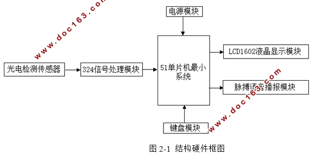
论文首先论证了单片机的型号选择,然后介绍了传感器以及显示芯片的型号选择。论文在系统硬件设计方面,首先给出总体的硬件框图,并分别对单片机、传感器、语音芯片的功能等进行了介绍,然后分别描述了单片机控制模块、数据采集模块、信号处理模块、按键模块、报警模块和液晶显示模块和按键模块的功能及设计过程。系统软件部分采用模块化的思想,给出了主程序,显示程序,控制程序以及语音播报程序的流程图。本文设计的脉搏计简单实用,成本低,适用人群广泛。
关键词:光电传感器 单片机 ISD1730 LCD1602
Pulse Tester Circuit Design
ABSTRACT
In this paper, the design was based on the microcontroller STC89C52.The design used photoelectric sensor, LCD1602 chip, ISD1730 chip and buzzer to realize the function of measuring the pulse meter and automatically display and broadcast data.This paper demonstrates the microcontroller model selection, and then introduces how to choose the sensor and display chip models .In the next system hardware design, the first hardware block diagram of the overall was introduced, and later to the microcontroller, sensors, voice chip features were introduced, and then describe the function of MCU control module, data acquisition module, signal processing module, a key module alarm module and LCD function modules and key module .System software modular thinking, given the flow chart of the main program ,display program, the control program and voice broadcast programs.This design of a pulse meter is simple,practical, low cost, wide application of the crowd.
Key Words: Photoelectric sensor; SCM; ISD1730 ; LCD1602


目 录
摘 要 I
ABSTRACT II
第一章 绪论 1
1.1 脉搏计的发展现状 1
1.2论文的研究内容 2
第二章 系统方案设计 3
2.1设计目标 3
2.2系统组成 3
2.3系统模块的交互 4 [来源:http://Doc163.com]
第三章 系统硬件电路设计 6
3.1 单片机控制模块电路设计 6
3.1.1 STC89C52简介 6
3.1.2 单片机控制电路 6
3.2 数据采集电路的设计 8
3.2.1 光电传感器简介 9
3.2.2 数据采集电路 9
3.3信号处理电路的设计 10
3.3.1 LM324简介 10
3.3.2 信号处理模块电路 11
3.4显示模块电路设计 13
3.4.1 LCD1602简介 13
3.4.2 显示模块电路 15
3.5语音播报模块电路设计 16
3.5.1 ISD1730简介 16
3.5.2 语音播报模块电路 17
3.6按键模块电路设计 18
3.7电源模块电路设计 19
第四章 系统软件设计 20
4.1主程序设计 20
4.2 定时和中断程序设计 21
4.3 显示程序设计 22 [资料来源:http://Doc163.com]
第五章 系统检测和调试 23
总 结 24
参考文献 25
致谢 26
附录一 27
附录二 28 [资料来源:www.doc163.com]
