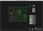
A市污水处理工程(80000m3/d污水厂)设计(含CAD图)

A市污水处理工程(80000m3/d污水厂)设计(含CAD图)(任务书,开题报告,外文翻译,计算说明书25000字,CAD图12张)
摘 要
根据该市的具体情况及出水要求,保证较好的出水水质,本设计采用传统A2/O工艺作为生物处理的主体工艺。由于A2/O的污泥龄较长,剩余污泥量较少,对污泥采用浓缩、脱水后直接泥饼外运即可。该工艺脱氮除磷效果好。
污水处理流程为:从格栅到泵房再到曝气沉砂池,从初沉池进入A2/O反应池,进入辐流式二沉池,完成污水的常规处理,污水进入机械絮凝池,进入斜管沉淀池,进入V型滤池,完成深度处理;最后排入河流。污泥的处理流程为:从二沉池排出的剩余污泥由污泥泵打入浓缩池,经过贮泥池储存,进入脱水机房,同时从初沉池流出的污泥由污泥泵打入脱水机房,最后外运处置。
关键词:生物处理;A2/O生物池;脱氮除磷
Abstract
According to the specific situation of the city and the requirements of effluent, the better effluent quality is guaranteed. The traditional A2/O process is adopted as the main process of biological treatment. As the sludge age of A2/O is longer, the amount of excess sludge is less, and the sludge can be concentrated and dehydrated directly. The process has good nitrogen and phosphorus removal effects. [来源:http://Doc163.com]
Sewage treatment process: from the grid to the pumping station to the aerated grit tank from the tank into the A2/O reactor, into the radial flow sedimentation tank two, conventional sewage treatment, sewage enters into the mechanical flocculation tank, inclined tube sedimentation tank, into the type V filter, to complete the most advanced treatment; after being discharged into rivers. Process for sludge from the sludge discharged from two sedimentation tank sludge pump into the concentration tank, through the mud storage tank storage into the dehydration room, at the same time from the primary settling tank out of the sludge pump into the dehydration room, finally Sinotrans disposal.
Key words: biological treatment; A2/O biological pond; nitrogen and phosphorus removal
设计概论
1.1 设计依据和设计任务
1.1.1 设计任务
1.设计题目:80000m³/d的污水厂设计。
污水厂实际最高日最高时处理水量为:城市混合污水量与污水厂自用水量之和。
Qmax=80000×(1+0.095)=87600m³/d [资料来源:https://www.doc163.com]
污水厂设计参数取值如下:
城市混合污水日变化系数Kd=1.30:;
城市混合污水总变化系数Kz=1.40。
所以该污水厂设计水量如下:
平均日平均时污水量Q=87600/1.4=62600 m³/d =724.5L/s;
最高日平均时污水量Qmax=62600×1.3=81000 m³/d =937.5L/s;
最高日最高时污水量Qmax=87600m³/d=1013.0 L/s。
水量表如下表:
项目 设计水量
m3/d m3/h L/s
平均日流量 6.26×10⁴ 2608.3 724.5
高日平均时流量 8.10×10⁴ 3375.0 937.5
高日高时流量 8.76×10⁴ 3650.0 1013.0
[来源:http://www.doc163.com]


目录
第一章 设计依据和设计任务 6
1.1.1 设计任务 6
1.1.2 设计内容和要求 7
1.1.3 设计原始资料 8
第二章 污水处理工艺简介 10
2.1 污水处理构筑物的选型 10
第三章 污水处理构筑物计算
3.1 格栅计算 14
3.1.1 设计参数 14
3.1.2格栅设计计算 14
3.1.3 格栅除污机的选择 17
3.2 污水泵房的设计 17
3.2.1 泵房的布置形式及布置原则 17
3.2.2 污水提升泵房的设计 18
3.3.1 沉砂池的作用 22
3.3.2 曝气沉砂池的设计 22
3.4 初次沉淀池 26
3.4.1 设计数据 26
3.4.2 刮泥设备的选择 28
3.4.3初沉池集配水井计算 28
3.4.4 沉淀池进水管路计算 30
3.4.5 拦浮渣设施及出水堰 31
3.5 A2/O生物池设计计算 32
3.5.1 设计参数 32
3.5.2 设计计算 33
3.6二沉池 45
3.6.1 设计参数 45
3.6.2 二沉池沉淀部分设计计算 45 [来源:http://www.doc163.com]
3.6.3 二沉池进水管路部分设计计算 47
3.6.4 沉淀池出水堰的计算 49
3.6.5 拦浮渣设施的选择 49
3.7 二沉池集配水井计算 50
3.7.1 设计参数 50
3.7.2 设计计算 50
第四章 污泥处理
4.1 污泥处理工艺流程 52
4.2 浓缩池 52
4.2.1 设计参数 52
4.2.2 设计计算 52
4.3 贮泥池 55
4.4 污泥脱水 57
4.4.1 污泥脱水量计算 57
4.4.2 脱水机的选择 58
第五章 中水处理
5.1深度处理工艺流程 59
5.2中水泵站 59
5.2.1设计依据 59
5.2.2 深度处理泵站 59
5.3 混凝反应的设计 60
5.3.1 混凝剂的选择 60
5.3.2 设计计算 60 [资料来源:http://www.doc163.com]
5.3.3 溶解池搅拌设备 61
5.3.4 药剂的投加方式, 61
5.3.5 计量设备 61
5.4 机械絮凝池计算 62
5.4.1设计水量的计算 62
5.5 斜管沉淀池 65
5.5.1设计流量 66
5.5.2平面尺寸设计 66
5.5.3进出水系统 67
5.6 V型滤池的设计与计算 70
5.6.1 平面尺寸的计算 70
5.6.2 进水系统 71
5.6.3 反冲洗系统 73
5.6.4 过滤系统 74
5.6.5 排水系统 75
5.6.6 滤池总高度 75
5.7消毒设计计算 73
5.7.1 加氯量计算 76
5.7.2加氯间和氯库 76
第六章 污水厂构筑物布置
6.1 平面布置 76
6.1.1 平面布置的一般原则 78
6.1.2 厂区平面布置形式 78 [资料来源:http://Doc163.com]
6.1.3 污水厂平面布置的具体内容 78
6.2 污水厂的高程布置 79
6.2.1 污水厂高程布置注意事项: 79
6.2.2 污水厂的高程布置 79
6.2.3高程计算 79
第七章 污水厂配套设施
7.1 变配电系统 79
7.2 监测仪表的设计 82
7.2.1 设计原则 82
7.2.2 检测内容 82
7.3 供热系统设计 82
第八章 污水厂定员
8.1 定员原则 83
8.2 污水厂定员 84
第九章 工程概算及其运行管理 85
参考资料 89
