
前置式发动机夹钳取力器的设计(含cad零件图和装配图)
前置式发动机夹钳取力器的设计(含cad零件图和装配图)(选题审批表,任务书,开题报告,中期检查表,毕业论文14600字,cad图纸6张)
摘要:本文设计了一种汽车发动机取力器,这种取力器由于其特有的优点所以应用广泛。现在很多专用汽车大多装有一个重要的零件,就是取力器。因此,设计一种容易操作、性能优越的取力器成为了一种必要。本文所研究的是一种结构紧凑,持续工作时间很长前置式发动机夹钳式取力器,它不受汽车离合器的干扰,只要发动机工作,不论离合器处于何种工作状态,取力器都能正常工作。因此发动机取力器的研发有着重要的意义。
关键词:发动机;齿轮;液压系统;汽车
Desicn of Front-engine Clamp Power-take
Abstract:This paper has designed an automobile power take off device. Because of its peculiar advantages, it was used so widely. Nowadays many special cars equip-ed with such most important part. Therefore, it is necessary to design an easy operation, superior performance of Power take . This paper studies a front loaded engine clam-p type Power take off device which has a compact structure and could continuous working for very long hours, it could be free from the clutch’s interference. As long as th-e engine works, no matter what kind of work in clutch state, take the force can work normally. therefore, the development of the device, which takes off the power from th-e engine,has a great significance. [版权所有:http://DOC163.com]
Key words:Engine;Gear;Hydraulic system;Car
本次设计的基本要求为:
1、取力器动力输出转向与发动机相同;
2、额定输出扭矩为800Nm;
3、额定输出转速为1500r/min;
4、速比为1:1左右;
5、取力器的结合与断开需要柔性连接。
[来源:http://Doc163.com]

[资料来源:http://doc163.com]
目录
摘要 2
关键词 2
1 前言 2
1.1 汽车发动机取力器的概况 2
1.2 研究发动机取力器的意义 2
2 取力装置简介 2
2.1 取力装置的功用和分类 2
2.1.1 发动机飞轮取力 2
2.1.2 离合器取力 2
2.1.3 变速器取力 2
2.1.4 分动器取力 2
2.2 取力装置的正确选择 2
3 总体方案设计 2
3.1 发动机取力器传动系统的设计 2
3.1.1 档位和旋向 2
3.1.2 取力器功率 2
3.1.3 取力器传动比和转速 2
3.2 齿轮传动设计与校核 2
3.2.1 材料的选用 2
3.2.2 按齿面接触疲劳强度初步设计 2
3.2.3 验算齿面接触疲劳强度 2
3.2.4 验算齿根弯曲疲劳强度 2 [来源:http://Doc163.com]
3.2.5 确定齿轮的主要参数及集合尺寸 2
3.2.6 确定齿轮制造精度 2
3.3 轴与轴系零件的设计 2
3.3.1 轴材料的选择 2
3.3.2 轴的结构设计 2
3.4 键的选择与校核 2
3.5 轴承的选择 2
4 内置离合器和液压系统的选择 2
4.1 液压多片摩擦离合器的选择 2
4.1.1 多片摩擦离合器的位置布置 2
4.1.2 多片摩擦离台器的结构特点 2
4.2 内啮合齿轮泵的选择 2
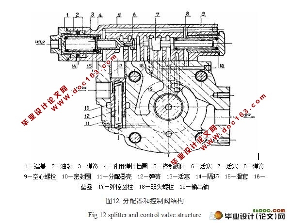
4.3 分配器和控制阀 2
5 结论 2
参考文献 2
致 谢 2