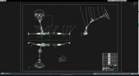
家用中型轿车(一汽马自达阿特兹)转向系设计(含CAD零件装配图)

家用中型轿车(一汽马自达阿特兹)转向系设计(含CAD零件装配图)(任务书,开题报告,文献摘要,外文翻译,论文说明书11000字,CAD图6张)
摘 要
本课题从实际角度出发,选取国内市场受众广泛的中型家用轿车为例(一汽马自达阿特兹2.0型),对其转向系统的形式、结构、转向器的结构选定、转向梯形的优化工程等做分析。此外还针对该结构进行强度验证,保证安全可靠的同时符合结构简单、紧凑、控制成本的工业化设计需求。本次研究包罗对转向体系的钻研背景阐述、转向系的布局剖析、转向器参数选定和计算、转向器结构强度校核、转向梯形布局的选型计较、转向操纵机构的设计计算以及转向传动机构的设计计算。题目中涉及到的知识以汽车构造教材、机械设计手册为基础,参考国内外的相关资料完成。
关键词:转向系统;齿轮齿条;转向梯形;转向器
Abstract
This project starts from a practical point of view and selects medium-sized family-cars with a wide audience in the domestic market as an example (FAW-Mazda Atenza 2.0). It analyzes the form of the steering system, the structure of the steering system, the selection of steering gears, and the optimization of steering trapezoidal structures. In addition, the strength verification of the structure is also performed to ensure safety and reliability while meeting the industrial design requirements of simple structure, compactness, and control cost. The content of this article includes background analysis of the steering system, structural analysis of the steering system, selection and calculation of steering gear parameters, checking of gear rack and pinion structure strength of steering gear, selection and calculation of steering trapezoidal structures, and design and calculation of steering mechanisms. Steering transmission design calculations. The knowledge involved in the topic is based on automotive construction textbooks and mechanical design manuals and is based on relevant domestic and foreign data.
Key words:Steering System; Rack and Pinion; Steering Trapezoidal; Steering
车辆参数选定
经由查阅相干资料,设计车种FAW-Mazda Atenza 2.0型的相关参数如下:
表1 车辆基本参数
轮距:前/后 1585/1575mm
轴距 2830mm
满载轴荷分配:前/后 1070/846(kg)
整备质量 /kg
1447(kg)
轮胎 225/55R17
主销偏移距a 90mm
轮胎压力P/MPa 0.25
方向盘直径
400mm
最小转弯半径 6m
方向盘转动圈数 3
转向节臂 200mm
[资料来源:Doc163.com]


[资料来源:http://Doc163.com]
目 录
摘 要 I
Abstract II
第一章 绪论 1
1.1汽车转向系统概述 1
1.2 国内外先进转向技术范例 2
1.2.1四轮转向系统 2
1.2.2 线控转向技术 2
1.3研究内容和课题构成 3
第二章 机械转向系统基本结构和参数选定 4
2.1 机械转向系统的基本结构 4
2.2 转向系统的性能要求 4
2.3转向器传动副的传动间隙 5
2.4 车辆参数选定 5
第三章 转向器总体设计计算 6
3.1 转向器的分类及设计选择 6
3.2转向轮侧偏角计算 6
3.3转向器传动比计算 7
3.4 齿轮齿条设计 9
3.4.1 齿轮齿条基本结构 9
3.4.2 齿轮参数确定 9
3.4.3确定齿条主要参数和几何尺寸 10
3.5 齿轮轴的设计 12
3.5.1齿轮齿条传动受力分析 12
3.5.2 齿轮轴轴径的确定 12
第四章 齿轮齿条转向器数据校核 14
4.1 齿条的强度校核 14
4.1.1 齿条受力分析 14
4.1.2 齿条齿部弯曲强度的计算 15
4.2 齿轮的强度计算校核 16
4.2.1 齿面疲劳强度计算 16
4.2.2 齿轮齿根弯曲疲劳强度计算 17
第五章 转向操纵机构的设计 18
5.1转向盘设计和尺寸的确定 18
5.2转向轴和转向管柱的结构设计 18
5.2.1 可溃缩式转向柱 18
5.2.2 转向轴上半轴计算 19
5.2.3转向轴下半轴的设计计算 20
5.2.4塑料销强度校核 20
第六章 转向传动机构的设计 21
6.1转向传动机构的原理及方案选定 21
6.2 转向梯形的设计 22 [来源:http://Doc163.com]
6.2.1 转向梯形机构概述 22
6.2.2 转向梯形及转向节臂的选型 23
6.2.3 转向节臂强度校核 23
6.3 转向横拉杆 24
6.3.1横拉杆长度计算 24
6.3.2 横拉杆截面尺寸计算 24
6.3.3横拉杆其他尺寸计算及校核 25
6.4球头销的设计 26
6.4.1球头销的选择 26
6.4.2 球头销强度计算校核 27
总 结 29
致 谢 30
参考文献 31
[来源:http://www.doc163.com]
上一篇:E-40D纯电动物流车的动力系统设计(含CAD装配图,CATIA三维图)
下一篇:重卡气压盘式制动器设计(含CAD零件装配图,CATIA三维图)
