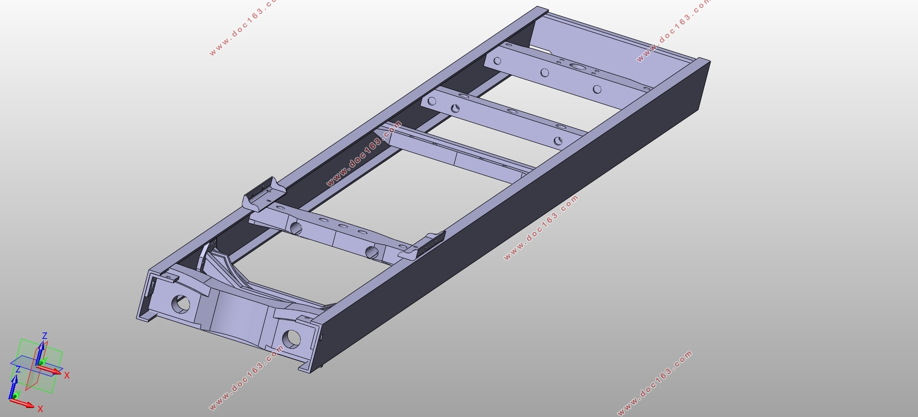
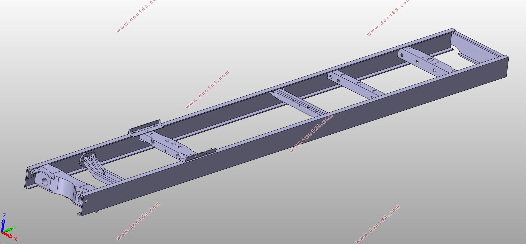
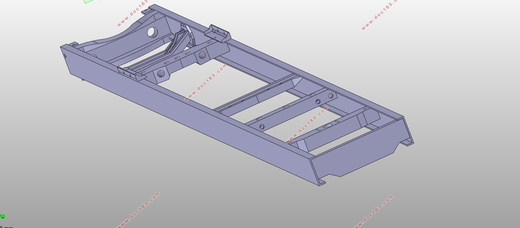
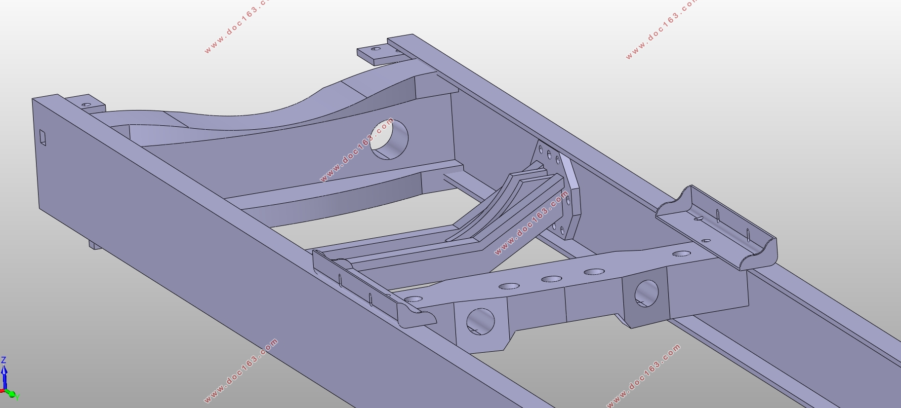
重型汽车车架三维设计(附CATIA三维图)

重型汽车车架三维设计(附CATIA三维图)(论文说明书9000字,CATIA三维图)
摘要
本文设计的课题是重型载货汽车的车架设计,研究对象为总重量14t以上的载货汽车,具有使用条件恶劣、负载高且随机性大等特点。本文首先对重型汽车车架的研究意义以及国内外对于载货汽车车架的研究状况作了简要介绍,然后通过对重型汽车的车架特点进行分析,根据国家及行业标准确定了车架结构与尺寸,论证了设计方案,并将车架简化为一个位于支座上的静定结构,进行了应力计算与强度校核,最后应用CAITA软件进行了三维实体建模,作出装配图。
关键词:重型汽车 车架 强度 三维建模
3D design of heavy truck frame
Abstract
The design issue is about the design of heavy truck frame. The research object is the truck with total weight of 14t. Under heavy loads, the working condition of heavy truck is extremely bad, and the stress condition is complex as well as varied. Firstly a brief introduction of the importance of the research and the condition of research at home and abroad is briefly introduced. Next, on the basis of national standards, the features of heavy truck frame are analyzed, then the structure and size is ensured and the design is demonstrated. Then, the frame is simplified as a determinate structure located on the bearing, so the stress can be calculated and the strength can be checked. Finally, based on the software CATIA, the 3d assembling drawing can be made.
[来源:http://Doc163.com]
Key words: heavy truck;frame;strength;3d model
确定研究车型及参数
研究车型为解放CA1198P11K2L2T1型载货汽车。
主要参数:总质量:19410kg 载重量:10000kg 外形长:8630mm
外形宽:2490mm 空载高:2730mm 满载前悬1255mm
满载后悬:2100mm 满载前轴负载:3890kg
满载中、后桥负载15520kg 满载前轴至中桥轴距:3925mm
满载中桥至后桥轴距:1350mm 前轮轮距:1914mm
中、后轮轮距:1847mm
[资料来源:http://doc163.com]


目 录
摘要 I
Abstract I
第一章 绪论 1
1.1 研究背景 1
1.2 国内外研究现状 1
1.2.1 车架材料与结构方面 1
1.2.2 有限元方法的应用 1
1.2.3 国内外研究现状 1
1.3 所要研究和解决的问题 1
1.4 采用的研究手段 1
第二章 设计方案选择 1
2.1 汽车车架的结构形式 1
2.2 边梁式车架的构成及特点 1
2.3 车架结构设计原则 1
第三章 车架结构与尺寸设计 1
3.1 确定研究车型及参数 1
3.2 确定车架的结构形式 1
3.2.1 确定车架基本尺寸 1
3.2.2 确定纵梁形式 1
3.2.3横梁的布置形式 1
3.2.4 确定车架材料 1
3.2.5 确定连接方式 1
第四章 车架应力计算与强度校核 1
4.1 建立力学模型 1
4.1.1 载荷分析 1 [版权所有:http://DOC163.com]
4.1.2 静态受载情况 1
4.2 强度计算 1
4.2.1 弯曲强度计算时的基本假设 1
4.2.2 支反力计算 1
4.2.4剪力图与弯矩图 1
4.3 校核 1
4.3.1 计算纵梁截面特性 1
4.3.2 计算弯曲应力及校核 1
4.3.3 校核临界弯曲应力 1
第五章 三维建模 1
5.1 CATIA软件介绍 1
5.1.1 CATIA软件的核心技术 1
5.1.2 CATIA的主要功能 1
5.1.3 建模思路及主要运用模块 1
5.2 零件设计 1
5.2.1 纵梁的绘制 1
5.2.2 第一根横梁的绘制 1
5.2.3 第二根横梁的绘制 1
5.2.4 第三根横梁的绘制 1
5.2.5 第四根横梁的绘制 1
5.2.6 第五、六横梁的绘制 1
5.2.7 第七横梁的绘制 1 [资料来源:http://doc163.com]
5.2.8 附属配件的绘制 1
5.3 装配设计 1
第六章 结论 1
参考文献 1
致 谢 1 [资料来源:www.doc163.com]
上一篇:轿房车后悬架(双横臂悬架)设计(含CAD零件图装配图)
下一篇:车身焊接生产线和夹具设计(含CAD零件图装配图,CATIA三维图)
