轿车辅助制动系统设计(附CAD图,CREO三维图)
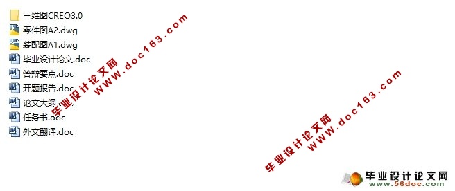
轿车辅助制动系统设计(附CAD图,CREO三维图)(任务书,开题报告,外文翻译,论文说明书13500字,CAD图纸2张,CREO图,答辩要点)
摘 要
随着汽车保有量迅猛增长,人们对车辆行驶的安全性能有了更高的标准。当遇到紧急情况驾驶员往往不能及时踩下制动踏板或踩踏力度不够,造成刹车距离过长。而辅助制动系统却可以很好地解决这一问题,它能够通过驾驶员踩下制动踏板的速度来判断是否遇到紧急情况。
本课题的研究是在参照众多专利产品的基础之上,以现有的轿车用真空助力器和与之配合工作的制动主缸为研究对象,设计出了一款新型机械式制动辅助系统。该新型机械式制动辅助系统通过对现有真空助力器结构上的改进,以达到紧急制动辅助的作用。
关键词:制动辅助;机械式;真空助力;改进;紧急制动
Design of Brake Assist System for Car
Abstract
With the rapid growth of car ownership, people have a higher standard for the safety performance of vehicles. When the emergency situation, ninety percent of the drivers in the braking operation, so that they can not be stepped on the brake pedal or pedal is not enough, resulting in long braking distance. The auxiliary braking system can be a good solution to this problem, it can be determined by the speed of the driver to step on the brake pedal to determine whether an emergency situation.
[资料来源:http://www.doc163.com]
The research on this topic is in reference on the basis of many patent products, the existing car vacuum booster and and with the work of the brake master cylinder as the object of study, design a new type mechanical brake assist system. Through the new mechanical brake assist system on the improvement of the structure of the existing vacuum booster, in order to achieve the role of auxiliary emergency braking.
Key words: Brake assist; mechanical; vacuum booster; improvement; emergency brake
本设计选取轿车上常用的直径为7寸的标准真空助力器为研究设计对象,与其配合的制动主缸的直径选为22.2mm。
[资料来源:www.doc163.com]
[版权所有:http://DOC163.com]
目 录
摘 要 II
Abstract III
1 绪 论 1
1.1本设计的研究的目的及背景 1
1.2 本设计的研究现状 2
1.3 本设计的研究方法 4
1.4 本设计的内容和目的 4
2 真空助力器工作原理的研究 6
2.1 操纵系统结构及原理 6
2.2 真空助力器的结构 6
2.3 真空助力器的工作原理 7
2.4 阀门的三个平衡位置介绍 8
2.5 两个平衡位置的介绍 8
3 真空助力器的特性(曲线)描绘 9
3.1 始动力Fa的计算 9
3.2 跳跃值JP的确定 10
3.3 释放力Fa1的确定 10
3.4 最大助力点E的计算 10
4 机械式 制动辅助 系统(MBA)结构及 其原理 11
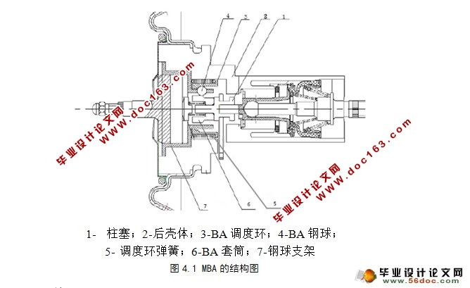
4.1 MBA的机械结构介绍 11 [版权所有:http://DOC163.com]
4.2 MBA的工作原理 11
5关键零件的尺寸设计 15
5.1 真空助力器的尺寸 15
5.2 橡胶反馈盘尺寸与过盈量 15
5.3 助力膜片的尺寸设计与校核 15
5.4 钢球的尺寸选择与校核 16
5.5 BA调度环与调度环弹簧的设计与校核 17
5.6 BA套筒及套筒弹簧的设计与校核 19
6 真空助力器标准零件的规定 21
6.1 装配尺寸链的计算 21
6.2 橡胶元件材料、邵尔硬度以及过盈量的规定 21
6.3 阀杆部分的强度检验 21
6.4 螺栓的强度校核 22
6.5 前壳体与后壳体的强度检验 22
6.6 锥形弹簧的选取与检验 23
7 小结 24
参考文献 25 [资料来源:http://www.doc163.com]
上一篇:汽车后翼子板成型工艺与模具设计(附CAD图,UG三维图)
下一篇:汽车座椅轻量化和舒适性的研究与有限元分析(含ProE三维图)
