铰链零件级进模具设计及数值模拟仿真(含CAD零件图装配图,UG三维图)

铰链零件级进模具设计及数值模拟仿真(含CAD零件图装配图,UG三维图)(任务书,开题报告,文献摘要,论文说明书26000字,CAD图17张,UG三维图,视频动画)
摘要
多工位级进模是一种先进、高效的冲压模具。它是一种多工位集成模具,是在单工序冲压模具的基础上发展起来的。对具有冲裁、弯曲、成形、拉深等多工序的各种冲压零件,它们的形状较为复杂的,用一副多工位级进模就可以完成这些零件的冲制过程。
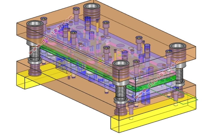
本次设计的是铰链零件的多工位级进模,包括铰链级进模的结构设计、U形弯曲回弹模拟和模具工作过程动画模拟。对铰链零件进行工艺分析,采用冲裁、卷圆、弯曲等加工工序,对铰链零件在条料上的废料进行设计并分组,绘制铰链零件的排样图。计算所有工位的工艺力大小,以此来选择压力机的型号,计算出模具的压力中心。成型零部件均采用镶块式设计,用挂台进行定位,这样来节省优质模具材料的使用,以减小模具报价。级进模采用向上弯曲设计和浮升销提升条料,卸料板与上模部分用限位螺钉和弹簧限位,使用弹性卸料装置。根据零件的卷圆部分结构特点,设计了斜锲、滑块组合的形式来完成横向卷圆成形。
在铰链级进设计的过程中,使用UG软件的PDW模块对铰链零件设置弯曲中性层系数,铰链零件展平为毛坯,并对级进模各个成型零部件进行三维实体建模,导入标准件及模架。将U形弯曲部分导出igs格式,导入DYNAFORM中,进行U形弯曲成型模拟及回弹模拟分析。将模型导入3ds Max软件中,进行铰链级进模的开合模动画和爆炸图仿真,以此来验证模具结构的合理性。
关键词:铰链;级进模;UG PDW;DYNAFORM;3ds Max动画
Abstract
Multi-position progressive die is an advanced and efficient stamping dies. It is an integrated multi-station mold developed form a single step stamping die. Some more complex shapes with punching, bending, forming, deep drawing and other processes of stamping parts can be completed in the multi-position progressive die.
This design is the hinge part multi-position progressive die. It includes a hinge progressive die design, U-bending spring back simulation and die working process animation. The forming process of the hinge parts has been analyzed in which punching, rolling, bending and other processing operations have been used. The scrap parts of the hinge on the strip have been designed and grouped. The layout figure of the hinge parts has been drawn.The stamping force of all process steps and pressure center of the mold has been calculated in order to select stamping equipment.
Molded parts are all designed to insert pieces, positioning with the convex plate, so as to save high-quality mold materials and reduce mold costs. Progressive die uses the design of upward bending and floating rising pin to lift strip. Stripper plate and the upper mold part are limited with a limit screw and spring retainer. The structural features of this crimping portion have been analyzedand the combination of oblique wedge and slider had been designed to complete transverse crimping forming.
[资料来源:www.doc163.com]
In the process of designing hinge progressive die, PDW module of UG software has been used to setting up the bending neutral layer coefficient of the hinge parts. Hinge parts have been flattened to blank. Some three-dimensional solid modelsof various progressive die parts have been created. Thestandard parts and die carrier have been imported. The U-shaped bending models have beenexported into DYNAFORM software in igs format and carried out the U-shaped bending forming simulation and spring back analysis. The whole modelshave been imported into 3ds Max software to performmoving process and exploded viewanimation of the hinge progressive die to verify the reasonableness of the mold structure.
Key words: Hinge; Progressive Die; UG PDW;DYNAFORM;3ds Max Animation
2铰链级进模模具结构设计
2.1 零件工艺分析及条料排布设计
2.1.1 铰链零件的工艺分析
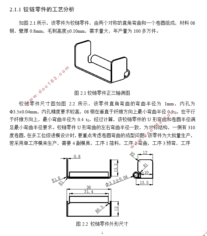
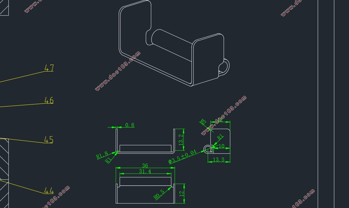
该零件为铰链零件,由两个对称的直角弯曲和一个卷圆组成,材料08钢,壁厚0.8mm,毛刺高度≤0.10mm,需求量大,年产量为100多万件。
[资料来源:http://doc163.com]
该零件直角弯曲的弯曲半径为1mm,内孔为Φ3.5±0.04mm,内孔精度要求较高,08钢在垂直于纤维方向上最小弯曲半径0.1t0,在平行于纤维方向上,最小弯曲半径为0.4 t0,经过计算,该铰链零件的U形弯曲和卷圆半径满足最小弯曲半径要求。铰链零件U形弯曲的左右弯曲半径一致,为对称结构,一侧有310度卷圆,在多工位级进模设计时,要重点考虑卷圆弯曲的成型问题。该零件为大批量生产,若采用单工序模来生产,需要4副模具,工序1落料,工序2弯曲,工序3预弯,工序
[来源:http://www.doc163.com]


 [资料来源:www.doc163.com]


目录
1 绪论 1
1.1 多工位级进模概述 1
1.2 国内外研究现状分析 1
1.3 课题研究的目的及意义 2
2 铰链级进模模具结构设计 4
2.1 零件工艺分析及条料排布设计 4
2.1.1 铰链零件的工艺分析 4
2.1.2 制件毛坯尺寸的计算 5
2.1.3 设计排样 7
2.1.4 绘制排样图 10
2.1.5 计算冲压力 12
2.1.6 压力机选型 15
2.1.7 压力中心的计算 16
2.1.8 模架的设计 17
2.2 级进模结构设计 18
2.2.1 冲裁零部件设计 18
2.2.2 对称U形弯曲成型凸凹模设计 25
2.2.3 卷圆弯曲成型零部件设计 28
2.2.4 限位装置设计 32
2.2.5 板料提升机构设计 32
2.2.6 模具工作原理 33 [来源:http://www.doc163.com]
2.3 UG级进模设计步骤 34
2.3.1 中间工步的建立 34
2.3.2 项目初始化与毛坯生存器 35
2.3.3 毛坯布局 35
2.3.4 废料设计 36
2.3.5 条料排样 36
2.3.6 冲压力计算 37
2.3.7 模架添加 37
2.3.8 冲裁镶块设计 38
2.3.9 折弯镶块设计 39
2.3.10 成型镶块设计 39
2.3.11 镶块辅助设计 41
2.3.12 标准件添加 41
2.3.13 让位槽设计 42
2.3.14 腔体设计 42
3 U形弯曲CAE分析 43
3.1 创建三维模型 43
3.3 初始设置 45
3.4 定义板料零件“BLANK” 46
3.5 定义凹模零件“DIE” 46
3.6 定义凸模零件“PUNCH”和压边圈“BINDER” 48 [来源:http://www.doc163.com]
3.7 模具初始定位设置 48
3.8 弯曲工艺参数设置 49
3.9 提交LS-DYNA进行求解计算 50
3.10 回弹设置 51
3.11 利用ETA/Post进行后处理分析 52
4 3ds Max动画制作 54
4.1 建模软件UG中零件的导出 54
4.2 将step文件导入到3ds Max 55
4.3 模型对象的分组 55
4.4 模具部分的关键帧设置 56
4.5 条料的关键帧设置 58
4.6 毛坯的变形设置 58
4.7 摄像机设置以及动画的导出 60
5 铰链级进模经济性分析 61
5.1 技术方案的经济性 61
5.1.1 铰链零件加工方案 61
5.1.2 最佳方案的确立 61
5.1.3 最佳加工方案的经济性分析 62
5.2 设计过程的经济性 62
5.2.1 采用三维造型软件设计模具结构 62
[资料来源:www.doc163.com]
5.2.2 使用DYNAFORM软件对重要成形进行模拟 62
5.2.3 使用动画检测模具运动的合理性 63
5.3 模具报价 63
5.3.1 经验计算法 63
5.3.2 材料系数法 63
5.3.3 报价方案的选择 64
5.3.4 标准件计算 64
5.3.5 非标准件计算 65
5.3.6 模具总费用 65
6 总结与展望 66
参考文献 67
致谢 69 [版权所有:http://DOC163.com]
上一篇:HP1020打印机送纸托盘的设计(含CAD零件图装配图,UG三维图)
下一篇:汽车转向节的锻模(模具)设计(含CAD图,答辩记录)
