复合材料浮筒封头热压成型模具设计(含CAD零件图装配图)

复合材料浮筒封头热压成型模具设计(含CAD零件图装配图)(任务书,开题报告,论文说明书15000字,CAD图20张)
摘要
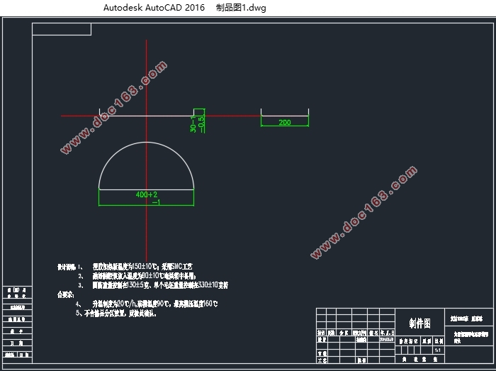
纤维复合材料具有轻质高强、耐低温、耐腐蚀、不生锈等优异性能,并且具有独特的可设计性,是制作轨太阳能电站浮筒封头的理想的材料。制作轨太阳能电站浮筒封头的成型工艺为模压成型工艺,而现在生产上所使用的成型模具大多为移动式模具,模具笨重,需要反复搬上搬下,劳动强度大,效率低,不利于生产。因而本设计就是针对现用模具的不足之处,进行改进设计,设计一副简单实用的成型模具,以便减轻劳动强度,提高生产效率,得到合格产品。本次设计从太阳能电站浮筒封头的图纸审查开始,主要包括了压制参数的设计、压模型式设计、成型方向、分型面选取、压机选择、成型零件设计、模具结构设计、强度设计、强度校核、模具功率计算、模具材质选择、模具的安装调试说明以及模具的保养和维修说明等方面,并且详细绘制出了浮筒封头的CAD图,模具装配和零件CAD图,各零部件型号选取以及模架结构选择依据国家相关标准。
关键词: 纤维复合材料;浮筒封头;模压成型;模具设计
Abstract
Fiber composite material have many excellent performance ,Like:lightweight, high strength, low temperature resistance,corrosion resistance, no rusting and can be designed with a unique character.So they are ideal materials to make solar power plant buoy head . Solar power production rail head float forming process for the molding process, mold production now used mostly for mobile mold, mold bulky, need to repeatedly move onto the next, labor-intensive, low efficiency, is not conducive to the production . Thus, the present design is for the deficiencies of the existing mold, to improve the design, design a simple and practical mold, in order to reduce labor intensity and improve production efficiency, to get qualified products. The review of design drawings from the solar power plant buoy Head Start, including the suppression of parametric design, die type design, molding direction, parting line selection, press select, mold design, molded part design, strength design, strength checking, power calculation mold, mold material selection, installation instructions mold and mold maintenance and repair instructions, etc., and a detailed map out of the buoy head CAD drawings, tooling and assembly parts CAD drawings, models of the parts Select and mold structure selection based on national standards.
Keywords: fiber composite ;float head ;molding ;mold design
[资料来源:www.doc163.com]


目录
第1章 绪论 1
1.1模压成型介绍 1
1.2 片状模塑料模压成型工艺流程 2
1.3 片状模塑料模压成型工艺对压模的基本要求 2
1.4 选题目的 3
第2章 设计部分 4
2.1 设计要求 4
2.2 设计依据 4
2.2.1 原材料选择 4
2.2.2 SMC一般参数 4
2.4 产品图纸 5
2.5 压模型式的选择 5
2.6 确定成型方向、分型面 5
2.6.1 成型方向 5
2.6.2 分型面 6
2.7 压力计算和压机选择 6
2.7.1 成型压力计算 6
2.7.2 开模力计算 6
2.7.3 液压机的选择 7
2.7.4 模结构间连接螺钉数 7
2.8 成型零件工作尺寸的计算 8
2.8.1 成型腔尺寸的计算 8
2.8.2加料室尺寸的计算 9
2.8.3 下模或模套壁厚尺寸计算 9
第3章 压模结构设计 11
3.1 下模结构设计 11
3.1.1 下模设计的基本要点 11
[资料来源:https://www.doc163.com]
3.1.2下模结构确定 11
3.2上模设计 12
3.2.1 上模设计的基本要求 12
3.2.2上模的基本形式 12
3.2.3 上模结构的确定 12
3.3 模架结构的设计 13
3.3.1模架结构的确定 13
3.4 成型零件的设计 14
3.4.1顶出机构的设计 14
3.4.2顶出机构的确定 14
3.5 压模导向机构的设计 14
3.6推板导柱的设计 15
3.7溢料槽的设计 15
3.8 加热系统设计 16
3.8.1 电加热装置 16
3.8.2 电热板和电热套 16
3.8.3 控制系统 16
3.8.4 压模功率的计算 16
3.8.5 电热棒选型和计算 17
3.9 压模型腔的确定 18
3.9.1压模型腔结构的优化 18
[资料来源:http://doc163.com]
3.10 脱模斜度的设计 18
第4章 绘制压模图纸 20
4.1根据设计数据编制压模设计图纸 20
第5章 压缩模强度校核 21
5.1 上凸模的强度校核 21
5.2 顶杆的强度校核 21
5.3 凹模的强度校核 21
5.4螺钉紧固件的强度校核 22
第6章 模具的安装与调试 23
6.1 上模的安装 23
6.2 下模的安装 23
6.3 压模的调整 23
6.3.1成型压力和保压时间的调整 23
6.3.2 上、下工作台行程、定位、移动速度的调整 23
6.3.3 加热系统调整 23
6.3.4 确定操作顺序 23
第7章 模具的使用、维护和修理 25
7.1 模具的使用安全 25
7.1.1 人员操作规范 25
7.1.2装置使用安全 25
7.2模具的保管与维护 25
7.2.1 模具保管 25
7.2.2 模具使用的现场要求 25
7.2.3 模具的标记 26
7.2.4 模具的防锈 26
7.2.5 模具的包装盒运输 26
7.3 模具使用期内的保养和修理 26
第8章 结束语 28
参考文献 29
致谢 30 [版权所有:http://DOC163.com]
上一篇:NF2-15支座压铸成形工艺与模具的设计(含CAD零件图装配图)
