连接支杆注射成型工艺与模具的设计(含CAD零件图装配图)

连接支杆注射成型工艺与模具的设计(含CAD零件图装配图)(任务书,开题报告,论文说明书10000字,CAD图4张)
摘要
本文主要研究的是连接支杆的注塑成型工艺与模具的设计。分析了连接支杆的工艺特点,包括材料性能、成型特性、结构工艺性等。介绍了连接支杆注塑模分型面的选择、型腔数目及分布、选择成型设备,并用Moldflow软件进行充型过程的数值模拟计算,包括温度、压力、时间等。重点介绍了浇注系统、成型零件、导向机构、脱模机构、斜导柱导滑的侧向抽芯机构的设计,采用一模两腔布置,侧向点浇口浇注系统,对侧方向采用斜导柱抽芯机构,然后利用推杆和推管共同作用推出制件。本模具结构稳定可靠,效果很好,塑件达到了规定的技术要求。选择标准模架,并对注塑机的工艺参数进行了校核。
关键词:注塑模;连接支杆;尼龙6
Abstract
This paper mainly studies the injection molding process and mold design method of connecting struts. The process characteristics of connecting struts are analyzed, including material properties, forming characteristics, structural manufacturability, etc. The selection of parting surface, the number and distribution of cavities, and the selection of molding equipment of injection mold for connecting struts are introduced. Moldflow software is used to simulate and calculate the filling process, including temperature, pressure and time. The design of gating system, molding parts, guiding mechanism, demoulding mechanism and lateral core-pulling mechanism with inclined guide post guiding and sliding are introduced emphatically. one mold and two cavities arrangement, point gating system and inclined guide post core-pulling mechanism are adopted in the opposite direction, and then the parts are pushed out by the joint action of push rod and push plate. The mold structure is stable and reliable, with good effect, and the plastic parts meet the specified technical requirements. The standard die set was selected and the process parameters of injection molding machine were checked. [资料来源:Doc163.com]
Key words:injection mold; Connecting struts; Nylon 6
1.1.4成型特性及条件
1)尼龙6吸水性大,因此塑料在注射前应保证足够的干燥,保持较低的含水量。
2)尼龙6熔融温度范围窄,熔融状态热稳定性差,极易分解。
3)尼龙6流动性极好,用螺杆式注塑机注射时宜用自锁式结构,并应加热,螺杆应带止回环。
4)尼龙6成型收缩率大,取向性较为明显,易发生缩孔、凹痕、变形等缺陷,因此成型时间、压力等要稳定[4]。
1.1.5结构工艺性
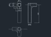
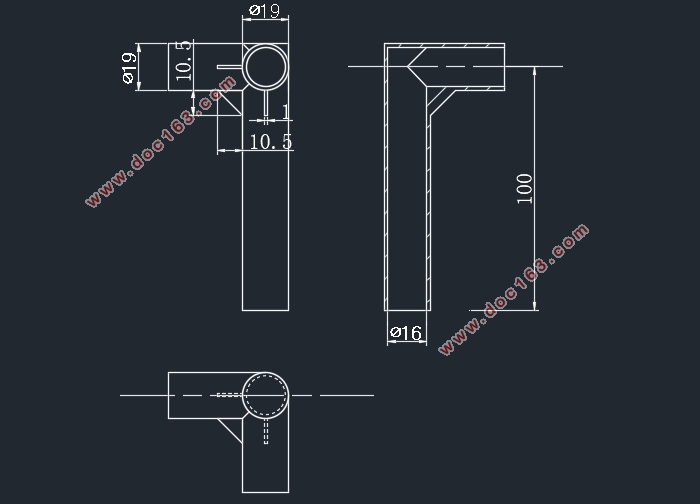
零件壁厚比较均匀,除加强筋处为1mm外,其余壁厚均为1.5mm。零件属于薄壁制件,成型时要特别注意。防止零件损坏。塑件为三根通管垂直相连的结构,零件外表面有3个加强筋,分别处于三根通管两两相交处。该制件虽然体积较小,结构较简单,但模具结构较为复杂,需用到抽芯机构,而且推出机构的推杆需要特别制作,推杆带防转销。
1.1.6零件体积及质量估算
1)单个塑件体积V=13.2cm3,质量m=14.9g。
2)浇注系统凝料浇注系统凝料按一个塑件体积的60%进行估算[5],则凝料体积V凝=13.2×60%=7.92cm3。
3)一模两腔的塑件和浇注系统凝料总体积V总=34.4cm3,总质量m总=38.87g。 [资料来源:www.doc163.com]
[来源:http://Doc163.com]


目录
第1章工艺分析与参数确定 1
1.1连接支杆工艺性分析 1
1.1.1塑料的发展 1
1.1.2课题来源 1
1.1.3材料性能 1
1.1.4成型特性及条件 2
1.1.5结构工艺性 3
1.1.6零件体积及质量估算 3
1.1.7连接支杆注塑成型工艺参数的确定 3
1.1.8初选注塑机的型号和规格 4
1.2 分型面与型腔数目 5
1.2.1确定模具基本结构 5
1.2.2分型面的选择 5
1.3 浇注系统的设计 7
1.3.1主流道的设计 7
1.3.2分流道设计 7
1.3.3浇口设计 7
1.3.4冷料穴设计 7
1.3.5浇口套和定位圈的设计 7
1.4 Moldflow充型模拟分析 8
1.4.1更改文件格式,导入模型 8
1.4.2划分网格 9
1.4.3创建流道 9
1.4.4连通性检查与设置参数 10
1.4.5分析结果 11
第2章模具结构设计 18
2.1成型零件设计 18
2.1.1凹模结构设计 18 [资料来源:http://Doc163.com]
2.1.2型芯结构设计 19
2.1.3主要模具零件的强度与刚度设计 20
2.2 脱模机构设计 21
2.2.1脱模力的计算 21
2.2.2推管脱模机构 21
2.3 侧向分型与抽芯机构设计 22
2.3.1抽芯距的计算 23
2.3.2斜导柱倾斜角 23
2.3.3斜导柱直径计算 23
2.3.4斜导柱长度的计算 23
2.3.5滑块的设计 24
2.3.6楔紧块的设计 24
2.3.7定位装置的设计 24
2.4 温度调节系统的设计 25
2.4.1 塑料传给模具的热量 25
2.4.2 需要用冷却水带走的热量 25
2.4.3 冷却水流量计算 26
2.5 模架及模具材料的选择 26
2.6 参数校核与模具调试 28
2.6.1 最大注射量的校核 28
2.6.2 注射压力的校核 28
2.6.3 锁模力的校核 28
2.6.4 模具闭合厚度校核 28
2.6.5 开模行程的校核 29
2.6.6 模具外形尺寸的校核 29
2.7成果展示 30
设计总结 32
参考文献 33
致谢 34
[版权所有:http://DOC163.com]
上一篇:盖板的模锻工艺及模具设计(含CAD零件装配图,UG三维图)
下一篇:POS-10端盖注射成形工艺与模具的设计(含CAD零件图装配图)
