盒盖塑料模具设计与制造(含CAD零件图装配图)

盒盖塑料模具设计与制造(含CAD零件图装配图)(论文说明书6000字,CAD图11张)
摘 要
近年来,塑料在电子工业中的应用范围日益扩大,以塑代钢、以塑代木得发展趋势越来越明显,尤其是塑料在收音机、录音机、电视机等电子产品及电风扇、洗衣机、电冰箱等轻功产品中的应用已占据了相当重要的地位。模具是塑料成型的主要工艺装备,也是产品更新换代的重要生产手段。随着现代塑料制品的形状越来越复杂,塑料模具的设计也越来越复杂。塑料模具的设计也从过去的“经验法则”的范围发展到了以计算机为基础量化、模拟化分析为手段的模具设计和制造的境界。塑料模具CAD/CAE与传统的设计方法相比,无论是在精确度、质量和速度方面还是模具的制造方法、生产率等方面都有一个显著的飞跃。注塑制品质量在很大程度上取决于模具设计,而浇注系统设计又是模具设计的重要组成部分。
关键词:塑料 模具设计 CAD/CAE 浇注系统
ABSTRACT
In recent years, the application field of plastic in the electronics industry is growing. The developing trends of using plastic in place of steel substitute and timber substitute become more and more obvious. Especially, plastic has occupied an important position in the application of electronic products, such as radio, recorder, TV sets etc and light industrial products, such as electric fans, washer, refrigerator etc. Mold is the main equipment and technology of plastic molding, also is the important means of product evolution. With the shape of the modern plastic products become more and more complex, the design of plastic mold is becoming more and more complicated. Plastic mold design has been developed from "rule of thumb" into use the computer as quantification and simulation analysis as means to design and manufacture mold. Compared with traditional design means, plastic mold CAD/CAE has a significant leap forward both in accuracy, speed, quality and the methods of mold manufacturing productivity and so on. The quality of injection molding product depends largely on the mold design, while the pouring system design is the most important part of it. [来源:http://www.doc163.com]
Keywords: plastic, mold design, CAD/CEA, pouring system
1. 塑件的工艺分析
1.1塑件的成型工艺性分析
产品名称:盒盖
产品材料:POM
产品数量:较大批量生产
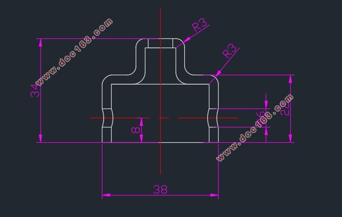
塑件尺寸:如图1所示
塑件重量:
塑件颜色:白色
塑件要求:塑件外侧表面光滑,下端外沿不允许有浇口痕迹。塑件允许最大脱模斜度0.5°
[来源:http://Doc163.com]


目录
摘 要 I
ABSTRACT II
1. 塑件的工艺分析 5
1.1塑件的成型工艺性分析 5
1.1.1 塑件材料POM的使用性能 6
1.1.2 塑件材料POM的加工特性 6
1.2 塑件的成型工艺参数确定 6 [资料来源:https://www.doc163.com]
2 模具的基本结构及模架选择 8
2.1 模具的基本结构 8
2.1.1 确定成型方法 8
2.1.2 型腔布置 8
2.1.3 确定分型面 8
2.1.4 选择浇注系统 9
2.1.5 确定推出方式 9
2.1.6 侧向抽芯机构 10
2.1.7 模具的结构形式 10
2.1.8 选择成型设备 11
2.2 选择模架 12
2.2.1 模架的结构 12
模架的结构如图6所示。 12
2.2.2 模架安装尺寸校核 12
3 模具结构、尺寸的设计计算 13
3.1 模具结构设计计算 13
3.1.1 型腔结构 13
3.1.2 型芯结构 13
3.1.3 斜导柱、滑块结构 13
3.1.4 模具的导向结构 13
3.1.5 结构强度计算 (略) 13
3.2 模具成型尺寸设计计算 13
[来源:http://Doc163.com]
3.2.1 型腔径向尺寸 14
3.2.2 型腔深度尺寸 14
3.2.3 型芯径向尺寸 14
3.2.4 型芯高度尺寸 15
3.3 模具加热、冷却系统的计算 15
3.3.1 模具加热 15
3.3.2 模具冷却 15
4. 模具主要零件图及加工工艺规程 17
4.1 模具定模板(中间板)零件图及加工工艺规程 17
4.2 模具侧滑块零件图及加工工艺规程 18
4.3 模具动模板(型芯固定板)零件图及加工工艺规程 19
5 模具总装图及模具的装配、试模 20
5.1 模具总装图 20
5.2 模具的安装试模 21
5.2.1 试模前的准备 21
5.2.2 模具的安装及调试 21
5.2.3 试模 22
5.2.4 检验 22
参考文献 23
总 结 24
致 谢 25 [资料来源:http://doc163.com]
上一篇:汽车进气歧管下壳模具结构设计及其成型过程CAE分析(含CAD图,SolidWorks三维
下一篇:盖板的模锻工艺及模具设计(含CAD零件装配图,UG三维图)
