扣板的成形工艺及模具设计(含CAD零件图装配图,UG三维图)

扣板的成形工艺及模具设计(含CAD零件图装配图,UG三维图)(任务书,开题报告,外文翻译,论文说明书15500字,CAD图14张,UG三维图)
摘要
扣板作为汽车上的零件,经常需要进行大批量生产,所以对生产效率的要求极高。传统的锻造技术成形后的扣板零件还需要进行切削加工,这样难以符合生产效率的要求。所以工业上,扣板的成形一般都采用精锻成形,这样可以既可以省去切削加工工序从而提高生产效率也可以提高扣板的成形质量。
本次设计先是对扣板的精锻成形工艺进行了设计,其次为了验证成形工艺的可靠性,使用了数值模拟软件DEFORM-3D按照成形工艺流程:制坯→预锻→终锻进行了数值模拟,其中DEFORM-3D中的模腔和坯料都是经过UG造型软件建模并导出的。最后,进行了整个锻模的设计,包括模座、导向装置、固定模块用的零件、顶出部分、模块、垫板。
DEFORM-3D模拟仿真后的结果,证明了扣板成形工艺选择的合理性、可靠性。因此,此次扣板的成形工艺和模具设计可以使用在工业生产中,为扣板的大批量生产带来方便。
关键词:扣板;锻造工艺;有限元;数值模拟
Abstract
As a part of a car, the buckle often needs to be produced in large quantities, so the demand for production efficiency is very high. The traditional forging technology needs to be machined after the forming of the pinch plate, so it is difficult to meet the requirements of production efficiency. Therefore, in the industry, the forming of the pinch plate is usually made by precision forging, which can save the cutting process, increase production efficiency and improve the forming quality of the pinch plate. [版权所有:http://DOC163.com]
This design is the first design of the forming process of plate forging, then in order to verify the reliability of the forming process, using the numerical simulation software DEFORM-3D according to the forming process: pre forging billet, forging, numerical simulation is carried out, the cavity in the DEFORM-3D and blank are derived by UG modeling software modeling and the. Finally, the design of the whole forging die is carried out, including the die block, the guiding device, the parts used for the fixing module, the ejector part, the module and the shim plate.
The result of DEFORM-3D simulation proves that the forming process is reasonable and reliable. Therefore, the forming process and die design of the pinch plate can be used in industrial production and bring convenience to mass production of the pinch plate.
Key Word: buckle;forging process; finite element method; numerical simulatio
设计的主要内容
此次设计以扣板为对象,对扣板的精锻成形工艺进行了设计,并且使用DEFORM-3D进行了扣板成形的有限元模拟分析。使用UG对扣板以及其锻模零部件进行了建模。具体内容如下: [资料来源:www.doc163.com]
1)根据所给扣板的工程图,使用UG造型软件对扣板进行了三维造型,从而能通过UG测量出扣板的体积和质量,以便与坯料尺寸的设计,并通过使用UG创建了扣板的成形模腔[7];
2)为了检验扣板成形工艺的可靠性,使用UG导出的模腔和坯料,在Deform-3D中进行数值模拟,预测金属在模腔中的填充效果、是否充满模膛以及成形所需载荷,从而也验证螺旋压力机的选择是否合适;
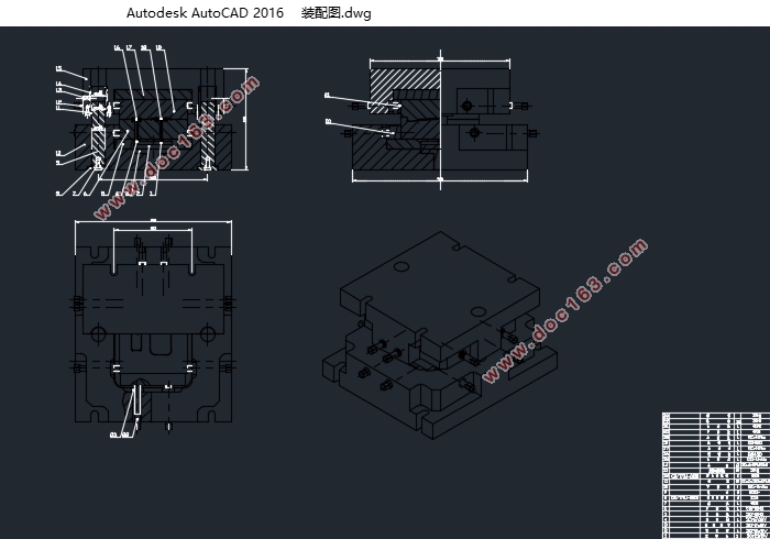
3)对扣板成形的锻模进行设计,使用UG绘制出模具的所有零部件,再通过UG的装配功能,将所有零部件装配起来,完成扣板成形锻模的三维造型。然后,将锻模三维装配图导出模具二维装配图以及各个零件图。
扣板零件图
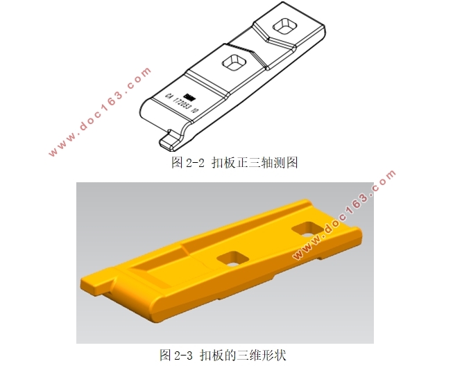
扣板是汽车上的重要零件之一,此次设计是对南京力聚精密锻造有限公司生产的扣板进行研究。南京力聚精密锻造有限公司生产的扣板CAD图如图2-1、图2-2所示为:
扣板形状为长形且 ,所以具体分为半长件,其形状复杂系数为S1[10]。
作为半长件锻件,扣板在成形过程中长度方向与宽度方向相比,变形会很小,因此扣板的锻造工艺选为有飞边的开式模锻,以宽度方向上先产生的飞边阻碍金属宽度方向上的继续流动,从而使长度方向上金属很好的充填模膛。另外,在坯料的选取上,也要尽可能使长度方向上尺寸接近所需尺寸,尽量使飞边的分布均匀。 [资料来源:Doc163.com]
[资料来源:http://www.doc163.com]


目录
第1章绪论 1
1.1 引言 1
1.2 精锻成形的发展现状 1
1.3 CAD、CAE在金属塑性成形中的应用. 2
1.4 设计的主要内容 3
1.5 小结 3
第2章扣板成形工艺 4
2.1 引言 4
2.2 扣板的材料特性 4
2.3扣板锻造工艺的分析 5
2.3.1扣板零件图 5
2.3.2 扣板成形工艺设计 6
2.3.3 扣板的热锻件图设计 8
2.4 预锻件设计 10
2.5 设备吨位选择 10
2.6 毛坯尺寸确定 11
2.7 小结 12
[来源:http://Doc163.com]
第3章扣板成形过程数值模拟 13
3.1引言 13
3.2锻造中的数值模拟技术 13
3.3 DEFORM软件的介绍 14
3.4 DEFORM-3D 操作 14
3.5 DEFORM-3D模拟前的操作 18
3.6 扣板成形过程的3D模拟 21
3.6.1 制坯工步的模拟结果分析 22
3.6.2预锻工步的模拟结果分析 22
3.6.3终锻工步的模拟结果分析 23
3.7 小结 24
第4章扣板锻模设计 26
4.1引言 26
4.2 模具结构设计 26
4.2.1 模架 27
3.2.2 模块 36
4.2.3 垫板 39
4.2.4 模具三维及CAD装配图 40
4.3 小结 44
第5章结论与展望 45
5.1 结论 45
5.2 展望 45
参考文献 46
[资料来源:www.doc163.com]
致谢 48
[资料来源:www.doc163.com]
上一篇:汽车车身覆盖件冲压成形工艺分析及模具设计(含SolidWorks三维图)
下一篇:顶罩件冲压工艺分析与模具设计(含CAD零件图装配图,PROE三维图)
