轴盖件冲压工艺与模具设计(含CAD零件装配图,PROE三维图)

轴盖件冲压工艺与模具设计(含CAD零件装配图,PROE三维图)(任务书,开题报告,论文说明书13000字,CAD图纸18张,PDF图纸18张,PROE三维图)
摘要
本文主要是对端盖的冲压工艺及其模具的设计。由零件图和工艺要求进行工艺方案的选择、排样设计以及冲压力的计算。结合实际生产的需要,在零件的工艺性设计以及在工艺方案的选择时,对复合模、单工序模、级进模的优缺点进行对比,选出合适的方案,对模具的基本结构和实际生产过程中的应用都有了进一步的了解。在工艺参数的计算中,对工作部分的外形尺寸进行了设计以及对压力机进行了选择。在对模具的总体设计时,有对零件的设计和强度校核,以及所用模架的选择。另外,级进模中的凹模采用镶块的方式,便于在实际生产过程的维修和保养。设计过程中的主要工序工位包括:冲孔工位,拉深工位,翻边工位,落料工位、压印工位。论文中对拉深工艺进行了有限元析,还对模具零件的加工工艺和模具的装配也进行了详细的叙述。本论文能够将所学专业课程的理论和实际生产过程相结合,对冷冲压模具设计的具体过程进行了设计。
关键词:轴盖件;冲压工艺;模具设计
Abstract
This paper mainly focuses on the stamping process of the end cover and the design of its die. Selection of process plan, layout design and calculation of stamping force are carried out according to part drawings and process requirements. According to the needs of actual production, the advantages and disadvantages of compound die, single-process die and progressive die are compared in the process design of parts and the selection of process plan, and the appropriate scheme is selected. The basic structure of the die and the application of the actual production process are further understood. In the calculation of process parameters, the shape and size of the working part are designed and the press is selected. In the overall design of the die, there are parts design and strength check, as well as the choice of the die holder used. In addition, the die in the progressive die adopts the way of insert, which is convenient for maintenance and maintenance in the actual production process. The main working positions in the design process include punching, drawing, flanging, blanking and printing. In this paper, the drawing process is analyzed by finite element method, and the processing technology of die parts and the assembly of die are also described in detail. This paper can combine the theory of professional courses with the actual production process, and design the specific process of cold stamping die design.
[来源:http://Doc163.com]
Key words:shaft cover; stamping process; die design
零件的工艺性分析
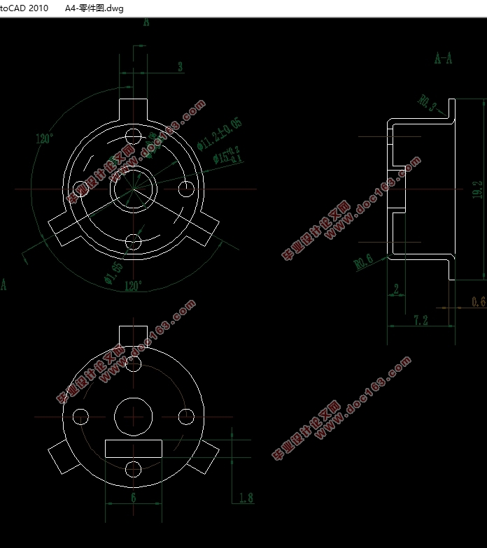
名称为轴盖零件,所用材料为SECC-SV,板厚t为0.6mm,由于轴盖件所用的材料为SECC-SV,其力学性能:τ=230~310Mpa,σ_b=275~380Mpa,σ_s=180Mpa。
由于对图样的形状精度要求较高,年产量大,可以确定精度为IT12级。由于制件不大,因此要在模具上设计好推件装置和取件方式;由于是大批量生产,对于需要保证模具的寿命,应重视模具材料的选择和模具结构的确定;当拉深的h/d较大时,应当考虑能否一次拉深,且最后一次拉深成型要保证R0.8的圆角;在翻孔前,要进行预冲孔,可以将冲翻孔预冲孔和冲四个小孔放在同一个工位。
2.2工艺方案的确定
该零件的制造包括冲孔工序、翻孔工序、落料工序、拉深工序四个基本工序,有三种方案可选择:
第一种方案:先进行落料,再进行拉深,再冲翻孔的预孔和四个小孔,再翻孔;
第二种方案:先拉深,再冲孔,再翻边,最后落料进行复合冲压,采用复合模生产;
第三种方案:进行拉深后,冲预孔,再翻孔,再落料级进冲压,采用级进模生产。
方案一虽然单个工序简单,但太繁琐,需六个步骤,因此也需要六副模具,经济效益不好,并且无法满足大产量生产要求,也可能导致半成品较多。方案二虽然也是只需一套模具,制造效率较高,但模具结构不好,模具容易损坏且不易维护,并且制造时间长,出件难。方案三需一副模具,不会产生中间的半成品废件,操作简单,模具维护相对简单,对工件的复杂程度无要求。 [资料来源:www.doc163.com]
通过分析比较,采用方案三。
[来源:http://www.doc163.com]


[资料来源:https://www.doc163.com]
目录
第1章绪论 1
1.1冲压模具简介 1
1.2我国模具工业的发展现状及发展趋势 4
第2章成形工艺设计及计算 6
2.1零件图及零件工艺性分析 6
2.1.1零件图 6
2.1.2零件的工艺性分析 7
2.2工艺方案的确定 7
2.3排样布置设计和材料利用率计算 8
2.4冲压力的计算 10
2.5拉深工艺的有限元模拟 12
第3章模具参数计算 14
3.1凸凹模尺寸计算 14
3.2压力机的选择 21
3.2.1压力机选择依据 21
3.2.2设备吨位 22
3.2.3压力机工作台面尺寸 22
3.3压力中心的确定与计算 22
3.4零件设计及强度校核 22
3.5模架的选择 26
3.6其他零件的选择 27
3.6.1定位和导正方式的选择 27
[资料来源:http://Doc163.com]
3.6.2导料板的设计 27
3.6.3卸料部件的设计 27
3.6.4模柄结构选择 27
3.6.5固定板的选择 28
3.6.6模具其他零件的选用 28
3.7模具成本计算 28
第4章模具的装配与加工 30
4.1模具的总装图 30
4.2模具装配工艺 31
4.3模具总装 32
第5章结论 33
参考文献 34
致谢 35 [版权所有:http://DOC163.com]
上一篇:风叶件冲压工艺与模具设计(含CAD图,PROE三维图)
