法兰盘连续模设计(含CAD零件图装配图)

法兰盘连续模设计(含CAD零件图装配图)(论文说明书7300字,CAD图纸13张)
Flange stamping process and die design
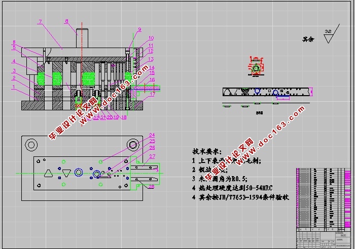
摘要 本文分析了电位器接线片的成型工艺特点,其中包括利用对工件展开图的尺寸计算、工件的工艺分析、冲裁力与拉深力的计算、模具设计的难点,确定了级进模的排样方案和模具总体结构。该级进模有冲裁、拉深、整形、胀形等7个工位。详细介绍了凸模、凹模、固定板、卸料装置等零部件的设计和制造,以及压力机的选择。同时阐述了模具的工作过程、各成形动作的协调性、以及凸模和凹模镶块的装配间隙,并制定典型零件的加工工艺
关键词:法兰盘 落料 翻边 级进模 模具设计
Flange stamping process and die design
Abstract This paper analyses the potential for the cable-forming process features, including the use of the workpiece size of the plan is launched, part of the process, punching power and drawing power, the difficulty of die design, identified the Progressive Die Die layout programmes and the overall structure. The Progressive Die a blanking, drawing, shaping, bulging, and other seven-position. Details on the punch and die, fixed panels, unloading devices, the design and manufacture of parts and components, and press option. At the same time on the work of the die process, forming the coordination of action and punch and die insert the assembly space and to develop parts of the typical processing technology
[资料来源:http://doc163.com]
Key words: Flange Blanking Flanging Progressive Die Die Design
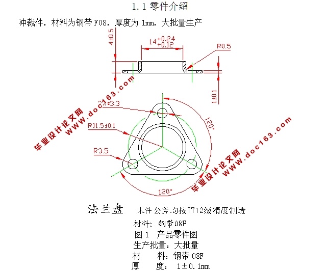
1.1零件介绍
冲裁件,材料为钢带F08,厚度为1mm,大批量生产
生产批量:大批量
材 料:钢带08F
厚 度: 1±0.1mm
1.2工艺分析:
(1)材料:该冲裁件的材料为黄铜带H65δ0.4M,具有较好的可冲压性能。
(2)零件结构:该冲裁件结构简单,尺寸及厚度都较小,中小批量生产,属普通冲压件,比较适合冲裁。
(3)尺寸精度:零件图上所有未标注的尺寸属于自由尺寸,可按IT14级确定工件的公差。
各尺寸公差为:
零件外形:14 mm , R4 mm,40.1 mm、3±0.5mm、19.9-00.08mm、1.6 mm
零件内形:R11.5±0.1mm、R3.5 mm、Φ3.3±0.05mm
孔心距:10.1±0.035mm、19.9±0.042mm、
结论:该零件适合冲裁。


目 录
引言…………………………………………………………………………4 [来源:http://Doc163.com]
第一章 冲压工艺与模具设计……………………………………………………5
1.1 零件介绍…………………………………………………………………5
1.2 工艺分析……………………………………………………………………6
1.3 工艺方案的确定……………………………………………………………6
1.4 工艺设计……………………………………………………………………7
[资料来源:http://doc163.com]
1.4.1 计算毛坯尺寸……………………………………………………………7
1.4.2 排样图……………………………………………………………………8
1.4.3 材料利用率………………………………………………………………8
1.5 计算冲压力…………………………………………………………………8
1.5.1 冲压力……………………………………………………………………8
[资料来源:http://www.doc163.com]
1.5.2 冲孔力……………………………………………………………………9
1.5.3 卸料力……………………………………………………………………9
1.5.4 推件力……………………………………………………………………9
1.5.5 初选压力机……………………………………………………………9
1.6 计算压力中心……………………………………………………………9 [资料来源:http://doc163.com]
第二章 工作零件刃口尺寸计算……………………………………………………10
2.1 凸凹模尺寸的计算………………………………………………………10
第三章 零件的工艺分析…………………………………………………………14
3.1冷冲压工艺卡片…………………………………………………………14
第四章 冲模零件机械加工工艺过程卡……………………………………………15
结论…………………………………………………………………………………22
致谢…………………………………………………………………………………23
参考文献……………………………………………………………………………24 [资料来源:http://Doc163.com]
上一篇:自行车脚蹬内板复合模设计(含CAD零件装配图,工艺卡)
