调料盒模具设计(含CAD零件装配图,成型工艺卡)

调料盒模具设计(含CAD零件装配图,成型工艺卡)(设计说明书15000字,CAD图纸5张)
摘要
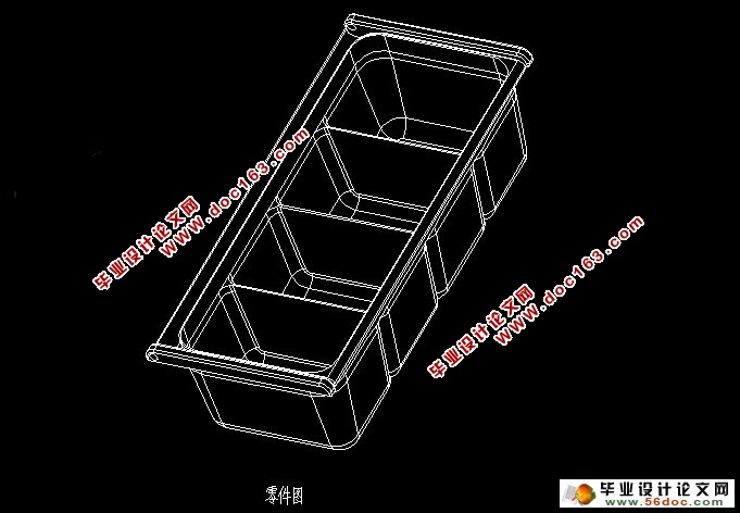
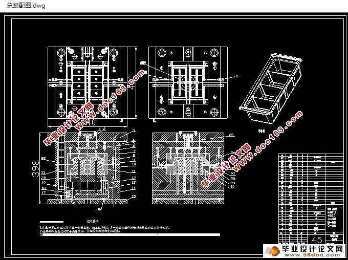
本次设计主要研究的是调料盒,在调料盒的塑料成型工艺跟模具方面进行设计。首先对塑件材料ABS,塑料件的尺寸精度,使用性能,表面质量,结构进行分析,然后利用CAD与PROE等软件对塑件的体积,重量,模具所需的塑料溶体注射量,锁模力等进行精确计算,随后可以暂定模具生产所需要的设备的选择,制定塑料成型工艺卡。重点在于注射模设计,首先分析可注塑性,对塑件表面质量不可忽视,表面不允许出现明显的接痕,和气泡伤疤,可以利用软件对注塑件可能出现的接痕和气泡进行分析。然后是可制造性,确定型腔数目,模具类型,模具主要结构,在模具主要结构设计中包括型腔布局,浇口的选择,型面设计,浇注系统设计,排气系统设计,导向机构设计,限位拉杆设计,随后可以确定模具的主要结构。然后选择模架,校准开模行程,计算推出距离,确定推出方式,设计侧抽芯机构,冷却系统,随之可以确定模具的总体结构。分析模具结构功能,其中包括型腔结构,型芯结构,型芯镶件结构,模具导向复位结构。计算成型零件工作尺寸,包括型芯尺寸,型腔尺寸。最后是模具的安装与试模,利用CAD绘制模具安装结构图。模具的具体工作过程是开模时,注塑机开、合模系统带动定模座板以后的部分后移,首先由橡胶、尼龙拉模扣的作用在水口板与定模板之间移动一段距离,把浇口里面的凝料拉断,拉杆端部的与动模座板接触,在带动水口板移动,把主流道里面的凝料拉出来,然后在定模部分的辅助分型面之间自行脱落或由人工取出,完成第一次分型。动模部分一起后移的同时斜滑块在弹簧给的弹力作用下带动侧型芯开始侧抽芯,动模继续后离,斜滑块也继续在弹簧的作用下完成侧抽芯,主分型面分型。因塑件包紧在型芯镶件上,随动模部分继续后移直至推出机构开始工作,注塑机的推杆在推出机构的作用下将塑件从型芯上推出,塑件在动模分型面之间自行脱落,完成第二次分型,即开模过程。合模时,模具在注射机推杆的作用下,由推杆推动推板在推动复位杆进行复位和导柱导套的定向作用,同时斜滑块在斜楔的作用下向里运动,压缩弹簧,完成合模过程。随后可以进行模具的安装试模,试模前需要一些检验模具闭合高度等的准备工作,然后可以进行模具安装调试,试模,检验完成整个模具设计。因为模具在现代生活中越来越高的使用率,设计模具的长寿命,合理性,模具成本的缩减就显得尤为重要,本次设计中就针对这几点进行了主要设计并取得了理想的预期效果,这次设计使我对现在国内模具发展生产状况有了一定的了解,在模具的合理设计方面有了一定的经验。
关键词: 注塑模; 调料盒; 长寿命
Abstract
The design of the main research is the condiment box,in the box of plastic molding process and mold design. First plastic material of ABS, the dimensional precision of plastic parts, performance, surface quality, structure analysis, and use CAD and proe software on the plastic parts of the volume, weight, plastic mold with the required solution injection quantity, clamping force etc. for accurate calculation, then can temporarily fixing mold production equipment and the development of plastic injection molding process card. Focusing on the design of the injection mold. Firstly, it analyzes the injection molding, and surface quality of plastic parts can not be ignored, the surface does not allow appear obvious marks, and the bubble scar, you can use the software of injection molded parts may occur after mark and bubbles were analyzed. The main structure and manufacturability, determine the number of cavity, the types of mold, die structure and in the design of the main structure of the mold including cavity layout, the choice of gate, surface design, gating system design, exhaust system design, the design of steering mechanism, limiting pull rod design, then you can determine the mold. Then select the mold base, calibration mould opening stroke calculation launch distance to determine the launch mode, design of side core pulling mechanism, cooling system, with the attendant can determine the overall structure of the mold. Analysis of mold structure function, including the cavity structure, core structure, core insert structure, mold guide reset structure. Calculate the working dimensions of the molding parts, including the core size, the size of the cavity. Finally, the mold installation and test mode, the use of CAD drawing die installation structure. Specific working process of mold is a mold, injection molding machine, synthetic simulation system drives the fixed mould seat plate part after the shift, first by the die of rubber and nylon buckle [来源:http://Doc163.com]
[来源:http://www.doc163.com]


[资料来源:Doc163.com]
目 录
引言 1
第一章塑件材料选择性能 3
1.1 ABS材料分析 3
1.2 塑料成型工艺性能分析 3
1.2.1 收缩性 3
1.2.2 流动性 4
1.2.3 热敏感性 4
第二章塑料件的结构工艺 6
2.1 塑料件的尺寸精度分析 6
2.2 塑料件的表面质量分析 6
2.3 塑料件的结构分析 6
第三章成型设备的选择和成型工艺的制定 8
3.1 成型参数的确定 8
3.2 塑件的体积和重量的计算 8
3.2.1 利用PRO/E进行体积的计算 8
3.2.2 四组调料盒重量的计算 8
3.3 模具所需塑料熔体注射量 9
3.4 锁模力的计算 9
第四章注射模设计 11
4.1 可行性分析 11
4.1.1 可注塑性分析 11
[资料来源:www.doc163.com]
4.1.2 可制造性分析 12
4.1.3 型腔数目的确定 12
4.2 确定模具的类型 13
4.3 确定模具的主要结构 13
4.3.1 模具型腔布局、浇口的选择 13
4.3.2 分型面的设计 15
4.3.3 浇注系统的设计 15
4.4 排气系统 18
4.5 导向机构的设计 18
4.5.1 导向机构的功用 18
4.5.2 导向机构的设计 18
4.5.3 设计导套和导柱须注意的事项 19
4.6 限位拉杆的设计 19
4.7 确定模具的主要结构 20
4.8 模架的选择 21
4.9 开模行程的校核与推出矩离 22
4.10 推出方式的确定 22
4.11 侧抽芯机构的设计 23
4.11.1 抽芯距 S抽 23
4.11.2 滑块与导滑槽的设计 24
4.12 冷却系统的设计 25
[资料来源:Doc163.com]
4.13 模具的总体结构 25
4.14 模具结构功能 26
4.14.1 型腔结构 26
4.14.2 型芯及型芯镶件结构 27
4.15 计算成型零件工作尺寸 27
4.15.1 型腔尺寸 27
4.15.2 型芯尺寸 28
第五章安装与试模 30
5.1 模具的安装结构图 30
5.2 模具工作过程 31
5.3 模具的安装试模 31
5.3.1 试模前的准备 31
5.3.2 模具的安装及调试 32
5.3.3 试模 32
5.3.4 检验 33
结论 34
参考文献 35
致谢 36
附录 37 [资料来源:Doc163.com]
上一篇:汽车模具新技术应用(纯论文)
