电阻自动成形机器模具设计(气压系统)

电阻自动成形机器模具设计(气压系统)(选题审批表,任务书,开题报告,中期检查表,论文说明书16900字,CAD图12张)
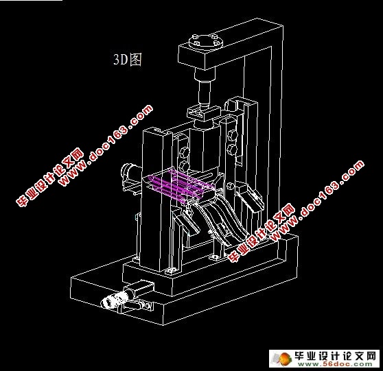
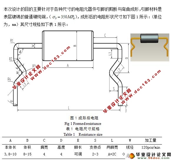
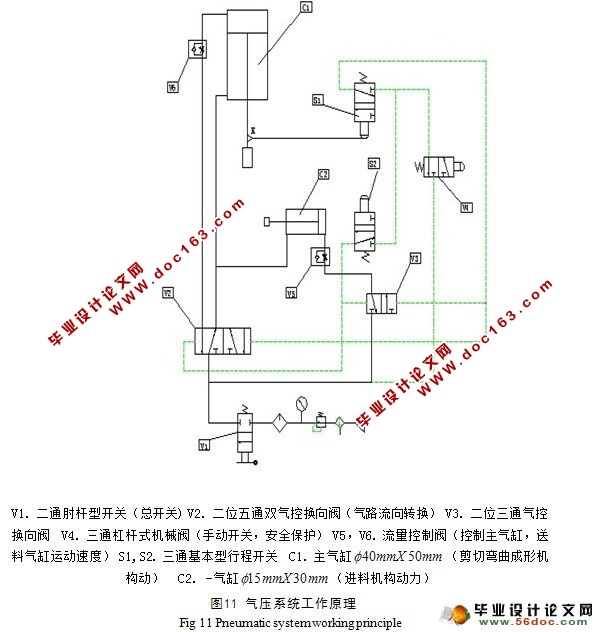
摘 要:设计本电阻自动成形机器模具主要是针对电阻引脚的最终成形生产。设计中分析了零件的结构及工艺性,拟订该零件的冲压工艺为“切引脚—弯曲引脚成形”,讨论了弯曲零件毛坯展开形状和尺寸的确定方法,设计了引脚切掉落料模和弯曲模,对关键零件的结构采用pro/e与CAD进行了详细的设计,并指出了模具设计时的注意事项。同时,运用pro/e软件对本次成形机器整体结构进行了设计,将弯曲成形模与切引脚落料模结合为一体组成复合模具,是本设计的重点,并采用气压自动控制系统,使得成形件的质量和生产效率较高,满足了生产需要由于模具设计是一种经验性较强的设计,经过长期发展积累了大量丰富的冲压工艺技术资料,在设计这两模具时必然要借鉴这些经验数据,含括了落料模、弯曲模、拉深模中常用的工艺数据以及模具材料的选取和气压系统各部件基本参数等等。
关键词:冲压工艺;毛坯;弯曲成形模;气动控制;自动成形;CAD;PRO/E;
The Automatic machine of Resistance forming
Abstract:Designs this automatic machine of resistance forming mold is in order to make the pins of the resistances forming shape finally .In the design has analyzed the components structure and the technology capab ility, drafts this components the ramming craft is “the cutting pins- - curving”, discussed the curving components semifinished materials to launch the shape and the size definite method, has designed the cut mpuld and the bending mould, has made the detailed elaboration to the essential components structural design in CAD and pro/E, and had pointed out the mold designed when matters needing attention., otherwise, Using pro/e software design the overall structure of the forming machine,and regroup with the bending forming mold and cutting pins mold as a Comprehensive mould, also use the automatic control system of air pressure,caused to flush a quality and the production efficiency is high, has met the production needs.Because the mold design is one kind of empirical strong design, passed through the long -term development to accumulate the massive rich ramming processing technology material, when designed these two sets of molds had to profit from these empirical data inevitably, including has included the cut mould, the bending mould, in the drawing mold the commonly used craft data as well as mold material selection and Pneumatic automatic control system basic para meter and so on. [资料来源:Doc163.com]
Keywords:Stamping Process;Semifinished Product;Bending Mould;Pneumatic Control;Automatic Forming;CAD;PRO/E;


 [资料来源:Doc163.com]
目 录
摘要..................................................................1
关键词................................................................1
1 前言................................................................2
1.1 冲压成形概述....................................................2
1.2 冲压成形的现状分析和特点........................................3
1.3 冲压成形的发展前景..............................................3
2 零件加工工艺分析....................................................4
2.1 零件尺寸材料分析................................................4 [资料来源:www.doc163.com]
2.2 电阻引脚长度计算................................................4
2.3 电阻排样与材料利用率的确定......................................5
3 剪切落料凸凹模设计.................................................6
3.1 引脚剪切力的计算................................................6
3.2 卸料力Fx的计算................................................7
3.3 推料力 的计算................................................7
3.4 成型机压力中心的确定...........................................7
3.5 冲裁模间隙值确定...............................................8
3.6 刃口尺寸计算的基本原则.........................................8
3.7 刃口尺寸的计算方法的确定.......................................9
3.8 计算凸,凹模的刃口的尺寸.......................................10 [版权所有:http://DOC163.com]
3.9 剪切落料凹模的设计.............................................10
3.10 剪切落料凸模的设计............................................11
4 引脚弯曲成形凸凹模设计.............................................12
4.1 弯曲件工艺性分析...........................................12
4.2 最小相对弯曲半径的分析与确定..................................13
4.3 弯曲成形回弹值的分析与确定.....................................14
4.4 影响回弹的因素及控制措施.......................................15
4.5 弯曲凸凹模圆角半径的确定.......................................16
4.6 弯曲力 的计算................................................16
4.7 弯曲部分刃口尺寸的计算.........................................17
5 气压控制系统的设计.................................................18
5.1 气压自动化简介.................................................19
5.2 空气压缩机的分析与选取.........................................19
5.3 气动执行元件的分析选取.........................................19
5.4 气缸基本尺寸计算...............................................20
5.5 气缸的选取.....................................................20
5.6 气动控制元件...................................................21
5.6.1 压力控制阀...............................................21
5.6.2 流量控制阀...............................................21
5.6.3 单向节流阀...............................................22
5.6.4 方向控制阀...............................................23 [版权所有:http://DOC163.com]
5.6.5 气压系统元器件...........................................23
5.7气动基本回路.....................................................24
5.7.1 一次压力控制回路.......................................24
5.7.2 换向回路.................................................24
5.7.3 双作用气缸速度控制回路...............................25
6 气压系统原理图设计..........................................25
7 成形机整体结构设计................................................27
7.1 机架结构的三维设计图...........................................27
7.2 定位夹紧装置设计图..............................................28
7.3 APP结构设计三维图..............................................28
[来源:http://Doc163.com]
7.4 机器结构总装图..................................................29
8 设计总结..........................................................29
参考文献.............................................................30
致谢..............................................................31
附录.....................................................................32
附录
附录1:装配图
附录2:上切刀
附录3:滑块
附录4:成形压头
附录5:落料凹模
附录6:定位夹紧装置
附录7:成型模
附录8:切除废料排出口
附录9:支撑架
附录10:冲头组合机构
附录11:联接滑块
附录12:气压系统
[资料来源:www.doc163.com]
