调温器的冲压工艺及模具设计(CAD,SolidWorks三维)
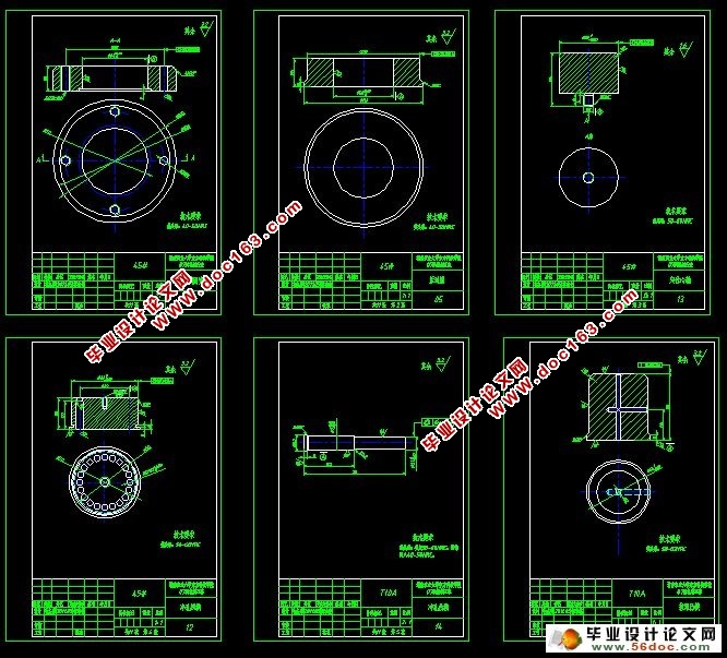
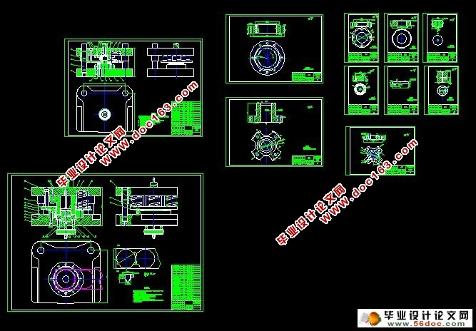
调温器的冲压工艺及模具设计(CAD,SolidWorks三维)(选题审批表,任务书,开题报告,中期检查表,论文说明书14000字,CAD图纸11张,SolidWorks三维)
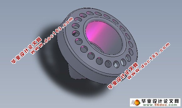
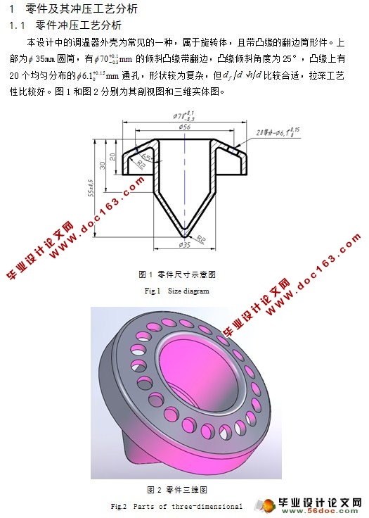
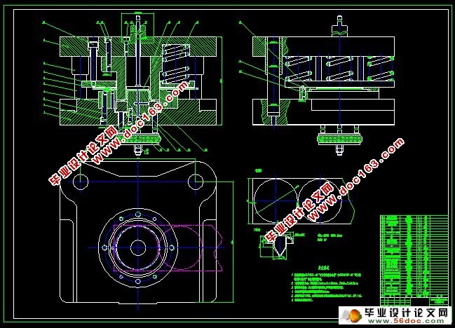
摘 要:冲压模具在实际工业生产中应用广泛,采用模具生产制品及零件,是现在工业生产的重要手段和主要发展方向。本次设计根据调温器外壳的结构特点,分析了它的冲压工艺,通过选择合适的工艺方案,进而对模具进行一步步的结构设计,最后设计出合理的冲压模具。该零件是调温器外壳,属于旋转体,且带有凸缘,凸缘末端还需外曲翻边,凸缘上均布20个小孔,形状较为复杂,但拉深工艺性比较好。零件采用 厚的08碳素结构钢制成,保证足够的刚度和强度。
关键词:冲压工艺;冲压模具;结构设计
Stamping Process and Die Design of the Thermostat
Abstract:Blunt press a molding tool an application is extensive in the physically industrial production, the mold production products and parts, is now an important means of industrial production and the main development direction.According to the thermostat shell structure characteristics, this design analyses its stamping process, by choosing appropriate process scheme, then the mold for structure design and finally step by step to design a reasonable stamping mold. This part is thermostat housing, belong to the revolver, and contain lugs, which should also end the song flanging and edgeunder 20 holes on the shape is relatively complex, but, deep drawing technology better. Parts adopt thick realige 08, ensure enough made the stiffness and strength.
Key word:Stamping process;stamping die;structural design
[来源:http://Doc163.com]
目 录
摘要 1
关键词 1
前言 2
1 零件及其冲压工艺分析 3
1.1 零件冲压工艺分析 3
1.2 冲压工艺方案的分析及比较 4
1.2.1 计算坯料的直径 4
1.2.2 锥形拉深前相关尺寸 6
1.2.3 计算拉深次数 7
1.2.4 确定工序合并与工序顺序 7
2 冲压工艺相关设计计算 8
2.1 确定排版、裁板方案 8
2.2 确定各工序相关尺寸 9
2.2.1 拉深工序 9
2.2.2 锥形拉深 10 [资料来源:https://www.doc163.com]
2.2.3 冲孔 11
2.3 计算各工序工作压力,选用压力机 11
2.3.1 落料拉深工序 11
2.3.2 第二次拉深工序 12
2.3.3 第三次拉深兼整形工序 13
2.3.4 冲孔工序 13
2.3.5 切边工序 13
2.3.6 翻边兼整形工序 13
2.4 冲压工艺过程表 14
3 模具结构形式的选择 14
3.1 落料拉深工序的模具选择 14
3.2 冲孔工序的模具选择 15
4 模具结构设计与相关计算 15
4.1 落料拉深复合模设计计算 15
4.1.1 模具工作部分尺寸和公差计算 15
4.1.2 卸料弹簧的选择 16
4.1.3 选择上下模板及模柄 16
4.1.4 凹模、凸模、凸凹模尺寸 16
[资料来源:www.doc163.com]
4.1.5 压边圈 16
4.1.6 推杆及顶板 17
4.1.7 闭合高度 17
4.1.8 卸料螺钉 17
4.1.9 导柱、导套 18
4.1.10 挡料销 18
4.2 冲孔模设计计算 18
4.2.1 模具工作部分尺寸和公差计算 18
4.2.2 凸模、凹模尺寸 19
4.2.3 卸料弹簧的选择 19
4.2.4 选择上下模板及模柄 20
4.2.6 闭合高度 20
4.2.7 导柱、导套 20
4.2.8 卸料螺钉 20
4.2.9 推杆及顶板 20
4.3 相关校核 20
4.3.1 凸模校核 20
4.3.2 顶杆抗弯能力校核 21
5 模具部分零件的加工工艺过程 21
5.1 凸凹模的加工 21 [来源:http://www.doc163.com]
6 模具装配工艺过程 23
6.1 装配的技术要求 23
6.2 模具的装配工艺过程 23
6.3 模具中的主要零部件的组装方法 23
6.3.1 模柄的装配 24
6.3.2 导柱、导套的装配 24
7 模具的调整 24
7.1 冲裁模的调整 24
7.1.1 送料不通畅或被卡死 24
7.1.2 卸料不正常,退不下料 24
7.1.3 凸、凹模的刃口相碰 24
7.1.4 凸模折断 25
7.1.5 凹模被胀裂 25
7.1.6 冲件的形状尺寸不正确 25
7.1.7 落料外行和冲孔位置不正,出现偏移现象 25
7.1.8 冲件不平整 25
7.1.9 冲件毛刺较大 25
7.2 拉深模的调整 25
7.2.1 制件拉深高度不够 25 [资料来源:Doc163.com]
7.2.2 制件拉深高度太大 25
7.2.3 制件壁厚和高度不均匀 26
7.2.3 起皱 26
7.2.4 制件有裂纹 26
7.2.5 制件表面拉毛 26
设计总结 26
参考文献 27
致谢 28
附录 28 [资料来源:https://www.doc163.com]
上一篇:连接片冲孔、翻边、落料连续式复合模设计(CAD,SolidWorks三维)
下一篇:汽车升降器的冲压工艺及模具设计
