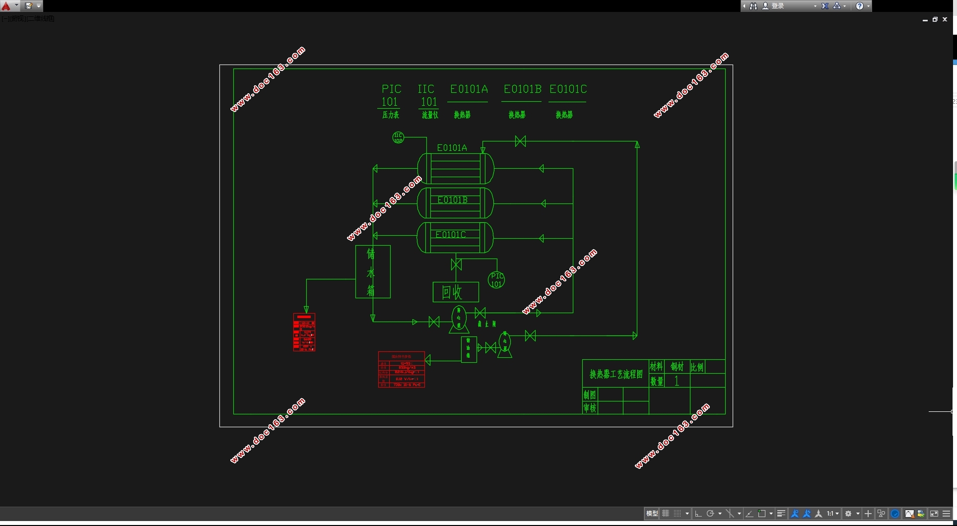
单壳程浮头式换热器设计(含CAD零件图装配图)

单壳程浮头式换热器设计(含CAD零件图装配图)(选题审批表,任务书,开题报告,中期检查表,外文翻译,论文说明书10000字,CAD图5张)
摘 要
换热器是化工生产中重要的设备之一,它是一种冷热流体间传递热量的设备,其中管壳式换热器应用最为广泛。本次设计为浮头式换热器,浮头式换热器主要由管箱、管板、壳体、换热管、折流板、拉杆、钩圈、浮头盖等组成。浮头换热器的一端管板与壳体固定,另一端为浮动管板。因此其优点为热应力较小,便于检查和清洗,其相较于固定管板式和U形管式的结构复杂,造价较高。
本次设计分工艺计算,结构设计和强度校核。在传热计算工艺中,包括传热面积计算,传热量、传热系数的确定和换热器内径及换热管型号的选择,以及传热系数、压降及壁温的验算等问题。在结构设计和强度校核中,主要讨论的是筒体、管箱、封头、管板以及折流板、法兰、垫片和接管、支座、分隔板等零部件的设计和强度校核。
关键词:换热器 强度校核 工艺计算 结构设计
Design of floating head heat exchanger using the single side shell
Abstract
Heat exchanger is one of the important equipment in the chemical production.It is a kind of equipment which cold and hot fluid transfer heat each other. Tube heat exchanger is used widely. The design is floating head heat exchanger. Floating head heat exchanger is mainly composed of tube box, tube plate, shell, heat exchange tube, baffle plate, rod, hook ring, floating head cover, etc. The end of floating head heat exchanger fixed tube sheet and shell, the other end is floating tube sheet. So its advantages is the thermal stress is lesser, facilitate inspection and cleaning. It compared with fixed tube plate and U tube type, it has complex structure, high cost. [资料来源:www.doc163.com]
The design has process calculation, structure design and strength check. In the heat transfer calculation process, it includes the heat transfer area computation the determination of heat transfer, heat transfer coefficient , the selection of heat exchange tube type heat exchanger and diameter ,calculating the heat transfer coefficient, pressure drop and the wall temperature and so on. In structure design and strength check. It discusses the design and strength check of the cylinder, pipe, head, tube plate and baffle plate, flange, gasket, and taking over, bearing, division plate parts.
Key Words: Strength check; Heat exchanger;Process calculation;architectural design
2.2 选择方案
1.2.1 换热器类型的确定 两流体的温度变化情况为煤油进口120℃,出口70℃;而水进口的温度35℃,出口的温度45℃。换热器的管壁温度和壳体温度差距比较大,所以选用浮头式换热器较为妥当。
1.2.2 流程的安排 从两流体工作压力来看,水是2MPa,煤油是1.9MPa,水走管程,煤油走壳程。而且工业水流速低,容易结垢,若其流速太低,加快污垢增长速度,则换热器传热能力下降,从总体考虑,水走管程,煤油走壳程。 [资料来源:http://www.doc163.com]
[资料来源:http://www.doc163.com]


目 录
摘要 I
ABSTRACT II
[资料来源:http://Doc163.com]
第一章 概述 1
1.1换热器用途 1
1.2换热器基本要求 1
1.3换热器分类 1
1.4换热器结构 1
1.5管壳式换热器 2
第二章 传热工艺计算 3
2.1初始数据 3
2.2选择方案 3
2.2.1 换热器类型确定 3
2.2.2 两个流体进入流程选择 3
2.3物性参数和定性温度 3
2.4热流量和冷却水流量 4
2.5计算平均传热温差以及估算传热面积 4
2.6选择管径和管内流速 4
2.7计算管程数和传热管数 4
2.8平均传热温差的校正和确定壳程数 5
2.9确定管心距和传热管排列 5
2.10壳程内径 5
2.11折流板 6
2.12接管 6
2.12.1 壳程流体进出口接管 6
2.12.2壳程流体进出口接管 6 [来源:http://Doc163.com]
2.13拉杆 6
2.14热流量校核 7
2.14.1 壳程表面的传热系数 7
2.14.2管内表面的传热系数 8
2.14.3 污垢热阻及管壁热阻 8
2.14.4传热系数K 8
2.14.5 传热面积S 9
2.15换热管内流体的流体阻力 9
2.15.1 管程流动阻力校核 9
2.15.2壳程阻力校核 10
2.16壁温核算 11
第三章 浮头式换热器的结构设计 11
3.1筒体内径的确定 11
3.2浮头管板和法兰结构设计 11
3.3管箱法兰和壳体法兰结构设计 12
3.4管箱结构设计 12
3.5固定管板结构设计 12
3.6外头盖法兰和外头盖设计 12
3.7选择垫片 12
3.7.1 管箱垫片 12
3.7.2外头盖垫片 12
3.7.3 浮头垫片 12 [来源:http://Doc163.com]
3.8折流板 12
3.9开孔补强 12
3.10支座 12
第四章 强度设计与校核 13
4.1设计计算条件 13
4.2浮头式换热器筒体计算 13
4.2.1计算条件 13
4.2.2厚度计算 13
4.2.3压力校核 14
4.2.4压力计算 14
4.3前端管箱筒体计算: 14
4.3.1计算条件 14
4.3.2厚度计算 15
4.3.3压力校核 15
4.3.4压力计算 15
4.4 前端管箱封头计算 15
4.4.1设计条件 16
4.4.2厚度设计 16
4.4.3压力计算 16
4.4.4水压实验 16
4.5后端管箱筒体计算 17
4.5.1设计条件 17
4.5.2厚度及重量计算 17
4.5.3压力试验时应力校核 18
4.5.4压力及应力计算 18
4.6后端管箱封头计算 18
4.6.1设计条件 18
4.6.2厚度及重量计算 19
4.6.3压力计算 19
4.6.4压力试验时应力校核 19
4.7接管及其法兰的计算 20
4.7.1筒体进料及出料接管计算 20
4.7.2管箱进料及出料接管计算 20
4.8浮头计算 21
4.8.1设计条件 21
4.8.2封头壁厚计算 21
4.8.3法兰厚度计算 22
4.9钩圈计算 24
4.9.1设计条件 24
4.9.2结果 24
4.10前端筒体法兰计算 24
4.10.1设计条件 25
4.10.2螺栓设计 25
4.10.3法兰力矩计算 27
4.10.4应力校核 28
4.11后端筒体法兰计算 29
4.11.1设计条件 29 [资料来源:http://doc163.com]
4.11.2螺栓设计 30
4.11.3法兰力矩计算 31
4.11.4应力校核 32
4.12前端管箱法兰计算 33
4.12.1设计条件 34
4.12.2螺栓设计 35
4.12.3法兰力矩计算 35
4.12.4应力校核 36
4.13后端管箱法兰计算 36
4.13.1设计条件: 37
4.13.2螺栓设计 37
4.13.3法兰力矩计算 38
4.13.4应力校核 39
结 论 41
参考文献 42
致 谢 43
上一篇:新型冷却器设计(含CAD图)
